Oil-water separator

The technology of oil-water separator and separation cylinder is applied in liquid separation, separation method, semi-permeable membrane separation and other directions, which can solve the problems of complex structure of automatic drainage mechanism, failure of timely drainage, and loss of automatic drainage function, etc., so as to improve work efficiency. Efficiency and working life, simple structure, high reliability effect

Inactive Publication Date: 2012-06-20
SANY HEAVY MACHINERY
View PDF1 Cites 0 Cited by
  • Summary
  • Abstract
  • Description
  • Claims
  • Application Information

AI Technical Summary

Problems solved by technology

However, the structure of the automatic drainage mechanism of this structure is relatively complicated, and at the same time it needs electrical components such as solenoid valves and power supplies, and the production cost is high. Once the delayer or other components fail, the automatic drainage function will be lost. Various hazards that can be drained in time

Method used


Image

  • Oil-water separator
  • Oil-water separator
  • Oil-water separator

Examples


Embodiment 1

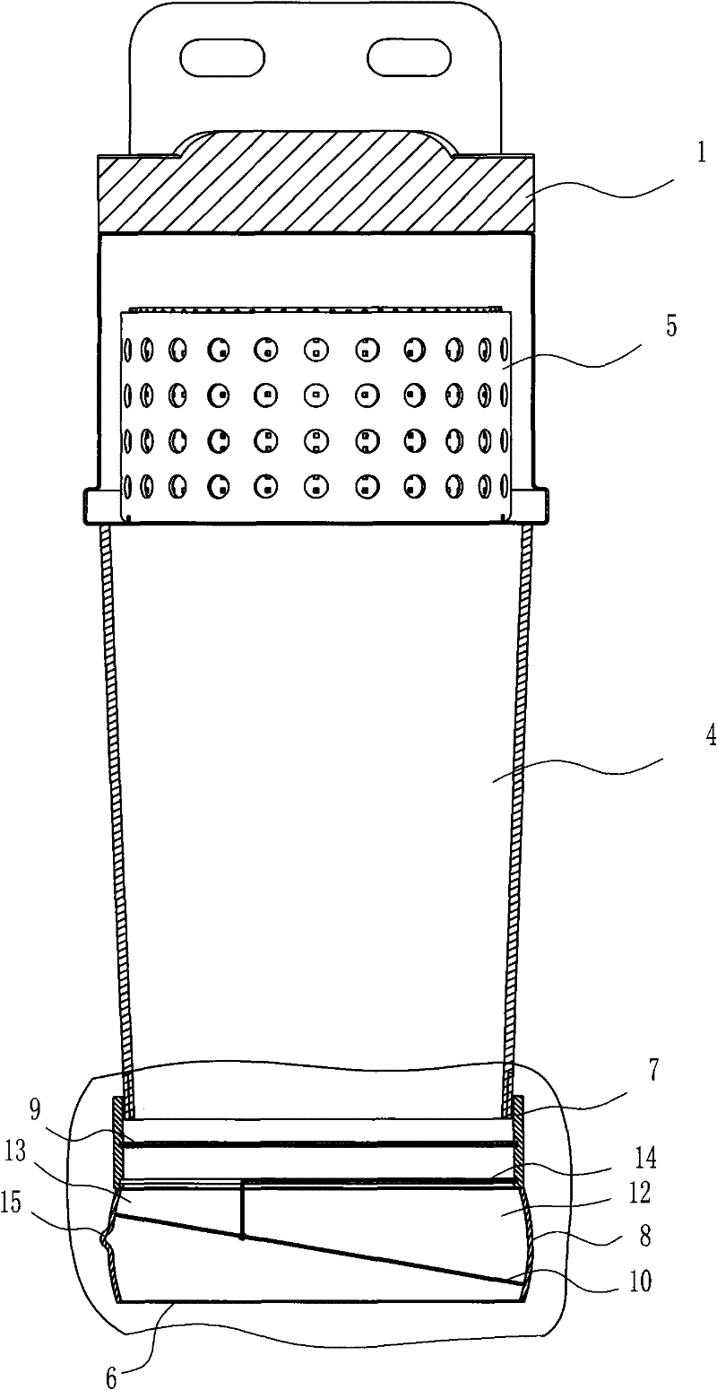
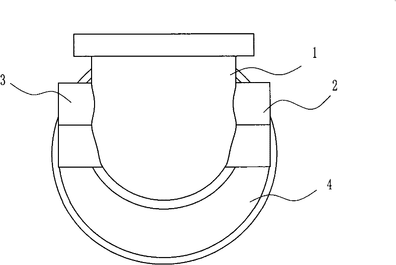
[0023] Embodiment one: see Figure 1~5 As shown, an oil-water separator includes a body and a water discharge mechanism at the bottom of the body. The top of the body is a base 1 provided with an oil inlet 2 and an oil suction port 3. Below the base 1 is a separation cylinder 4. The base 1. A water retaining plate 5 is provided on the top of the separation cylinder 4. The top inner wall of the water discharge mechanism is provided with an internal thread, which is screwed with the external thread at the bottom of the body. The bottom of the water discharge mechanism is provided with a water outlet 6. The water discharge mechanism The mechanism includes a water storage unit 7 and a water discharge unit 8;

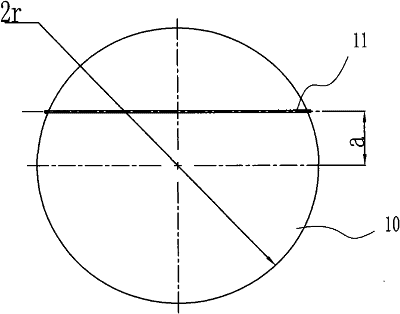
[0024] The top of the water storage part 7 communicates with the inner cavity of the separation cylinder 4, and an annular clamping groove is arranged in the described water storage part 7, and an oil-water separation membrane 9 is arranged in the annular clamping groove (th...


PUM


Abstract

The invention discloses an oil-water separator. The oil-water separator comprises a main body and a water draining mechanism at the bottom of the main body and is characterized in that: the water draining mechanism comprises a water storage part and a water draining part; a water-oil separation membrane is arranged in the water storage part; the water draining part has an arc-shaped inner wall; awater draining plate is arranged in the inner cavity of the water draining part; the water draining plate has a degree of freedom, through which the water draining plate can revolve around an eccentric shaft thereon; the outer edge of the water draining plate is matched with the arc-shaped inner wall of the water draining part; a water draining part above the water draining plate is divided into a cavity A and a cavity B by the eccentric shaft; the mass of the water draining plate corresponding to the cavity A side is equal to the sum of the mass of the water draining plate corresponding to the cavity B side and the preset starting water draining mass; a sunk part is arranged on the inner wall, corresponding to the cavity B side, of the water draining section; and the sunk part is positioned below the initial state of the water draining plate on the cavity B side and is communicated with a water outlet below the water draining section. In the oil-water separator, the water draining plate can revolve around the eccentric shaft according to the mass difference of the cavity A and the cavity B, so automatic drain of the water draining mechanism can be opened and closed and the quality of fuel oil entering a diesel is guaranteed.

Description

technical field [0001] The invention relates to an oil-water separation device, in particular to a separator for diesel oil and water used in construction machinery, so as to improve the purity of oil used and reduce the wear on components such as oil pumps. Background technique [0002] Diesel engines are widely used in large hydraulic excavators, and diesel oil will inevitably be mixed with water and other impurities during storage and transportation. Using diesel with water and other impurities will prematurely block the fuel filter, making the precision components The fuel pump and fuel injector etc. are malfunctioning. In order to avoid or reduce various failures caused by poor diesel quality, it is necessary to filter the fuel and separate the water in the fuel before the fuel enters the fuel pump and injector. Usually, oil-water separation is installed on the fuel inlet. filter to filter the impurities in the fuel and separate the contained water. [0003] The princ...

Claims


Application Information

Patent Timeline
Patent Type & Authority Patents(China)
IPC IPC(8): B01D17/032B01D17/12B01D61/00
Inventor 戴晴华孙琳陈志强
Owner SANY HEAVY MACHINERY
Why Eureka
Try Eureka