Adjustable cervical interbody fusion cage

An intervertebral fusion device, an adjustable technology, applied in the field of medical supplies, can solve the problems of cervical bony endplate injury, increase the pain of patients, and cannot adjust the inherent height and angle, so as to prevent collapse and kyphosis, and prevent spinal Compression symptoms, the effect of relieving nerve root compression

Inactive Publication Date: 2011-02-16
申勇
View PDF4 Cites 16 Cited by
  • Summary
  • Abstract
  • Description
  • Claims
  • Application Information

AI Technical Summary

Problems solved by technology

At this time, re-pruning will cause the height of the titanium mesh cage to be lost, and the replacement of the titanium mesh cage will take a lot of time
This undoubtedly affects the operation rhythm, prolongs the operation time and increases the suffering of patients.
And pulling out the titanium mesh cage will inevitably cause damage to the cervical bony endplate, which will adversely affect the postoperative fusion effect, the restoration and maintenance of intervertebral space height
2) Most of the clinically used cervical spine cages are made of polyetheretherketone (PEEK) material, which is processed and formed on the production line at one time. Although different models can be selected during the operation, the models are extremely limited and cannot meet the diversity of conditions of many patients at all.
The cage cannot be trimmed during the operation, that is, its inherent height and angle cannot be adjusted, and it is not adjustable
If the angle of the cage is found to be inappropriate after being implanted in the intervertebral space, it cannot be adjusted in any way. To replace the cage, it must be hammered forcefully and gradually pulled out of the intervertebral space. This will undoubtedly vibrate the spinal cord and damage the bones to varying degrees. sex endplate

Method used


Image

  • Adjustable cervical interbody fusion cage
  • Adjustable cervical interbody fusion cage
  • Adjustable cervical interbody fusion cage

Examples


Embodiment Construction

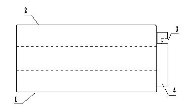
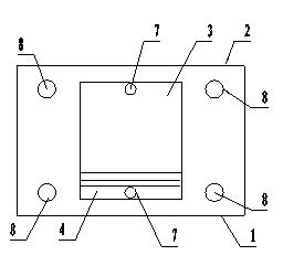
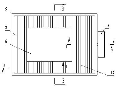
[0021] see Figure 1-3 , the composition of the present invention includes a main body structure and a sliding lock, and the main body structure is composed of two rectangular upper main boards 2, a lower main board 1, and polyester tension ligaments wrapped around the upper and lower main boards. 5, the upper and lower main boards are made of polyether ether ketone (PEEK) material, they form the frame of the main structure, and the bone groove 6 is set in the middle of the main structure, and the sliding lock is used to adjust and lock the relative position of the upper and lower main boards. Location.

[0022] see Figure 4 , Figure 5 , the I-shaped support linkage shaft 9 is symmetrically arranged in the middle of the two sides of the upper and lower main body plates. 9 and liner 11 are titanium metal parts. While the supporting linkage shaft provides support for the main structure, it can also play the role of connection and movement similar to the joints of the human...


PUM


Abstract

The invention discloses an adjustable cervical interbody fusion cage, which is used for solving the problems of low applicability, adjustment incapability and inconvenient intraoperative operation of an interbody fusion cage. The technical scheme is that: the adjustable cervical interbody fusion cage comprises a main body structure and a sliding lock; the main body structure consists of upper and lower main body plates which are separately arranged, and a polyester tensile belt coated around the upper and lower main body plates; a middle part of the main body structure is provided with a bone-accommodating groove; middles parts of two sides of the upper and lower main body plates are symmetrically provided with I-shaped support coupling shafts; upper shafts and lower shafts of the support coupling shafts are rotatably connected with the upper and lower main body plates through a pad respectively; and the sliding lock is positioned at one end of the main body structure. The angle adjustment function of the adjustable cervical interbody fusion cage makes the whole system more accord with the human body structure, facilitates the arrangement of the system, and integrates the system into a support structure of the vertebral column to accord with the human body mechanics, and the excellent postoperative fusion also reduces hazards of fracture and removal of an anterior cervical spine steel plate and a bolt.

Description

technical field [0001] The invention relates to a medical operating appliance, in particular to an adjustable cervical intervertebral fusion device used in anterior cervical surgery, and belongs to the technical field of medical supplies. Background technique [0002] Cervical spondylotic myelopathy and cervical spondylotic radiculopathy are common and frequently-occurring diseases of middle-aged and elderly people. With the change of lifestyle, the incidence rate is also increasing year by year, and it shows a younger trend. The pathogenic mechanism of cervical spondylosis is that the cervical intervertebral disc protrudes backward after degeneration, or the posterior edge of the vertebral body hyperosteogeny forms osteophytes that compress the spinal cord and nerve roots in the cervical spinal canal. Because the nerve cells in the spinal cord tissue are very fragile, the compression causes The loss of nerve function caused by pathological changes such as ischemia and hypox...

Claims


Application Information

Patent Timeline
Patent Type & Authority Applications(China)
IPC IPC(8): A61F2/44A61B17/70
CPCA61F2/44A61F2002/30001
Inventor 李鹏飞申勇张为丁文元
Owner 申勇
Why Eureka
Try Eureka