
Box lock mechanism

A box and cash box technology, which is applied in the field of self-service equipment cash box locking devices, can solve the problems of low reliability of the lock structure, achieve the effects of increasing service life, improving safety performance, and avoiding precision

Active Publication Date: 2011-02-16
GRG BAKING EQUIP CO LTD
View PDF4 Cites 15 Cited by
  • Summary
  • Abstract
  • Description
  • Claims
  • Application Information

AI Technical Summary

Problems solved by technology

[0006] The invention solves the technical problem of low reliability of the existing lock structure

Method used


Image

  • Box lock mechanism
  • Box lock mechanism
  • Box lock mechanism

Examples


Embodiment Construction

[0023] The embodiments described below are only some of the embodiments of the present invention, not all of them. Based on the embodiments of the present invention, all other embodiments obtained by persons of ordinary skill in the art without creative efforts fall within the protection scope of the present invention.

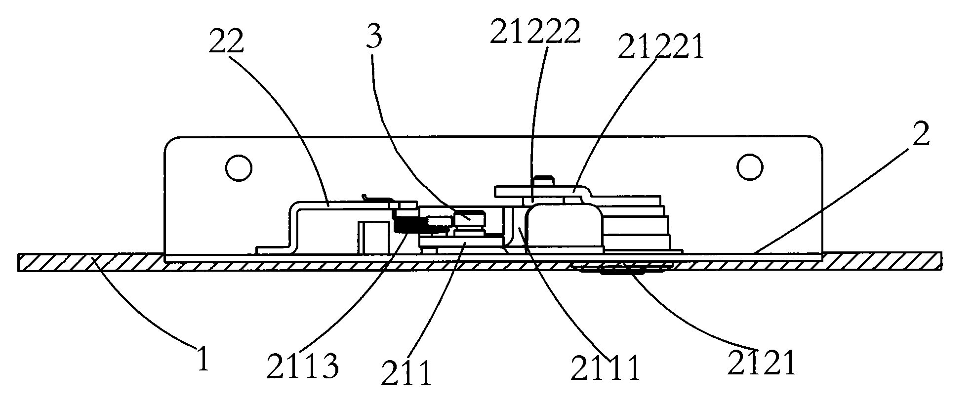
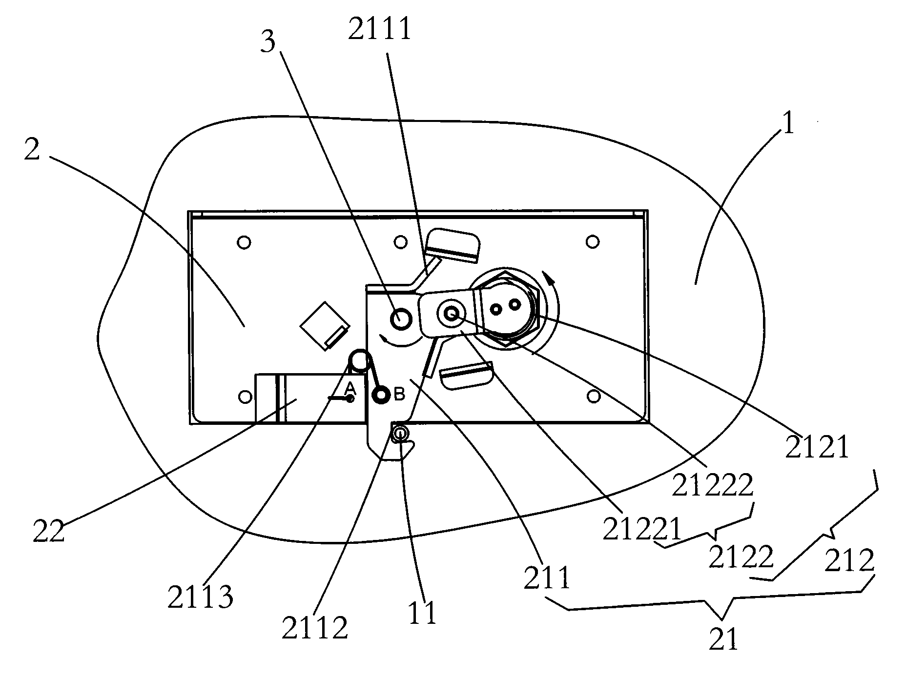
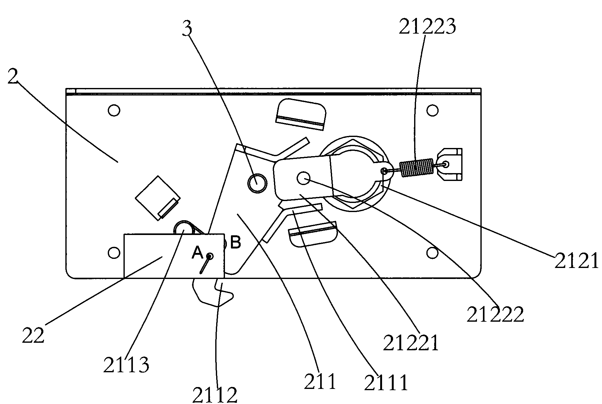
[0024] refer to figure 1 and figure 2 , a schematic diagram of the main part of a cash drawer safety lock mechanism provided by the present invention, the cash drawer safety lock mechanism is installed between the cash drawer body 1 and the sliding door 2, which includes the cash drawer body 1 and the sliding door respectively 2 on the lock arm buckle member 11 and the movable lock arm assembly 21, the movable lock arm assembly 21 includes a lock arm 211 that is movably connected to the sliding door through the rotating column 3, and a drive that drives the lock arm 211 to rotate The driving part 212; the first end of the lock arm 211 protrudes two plectrum...


PUM


Abstract

The invention solves a technical problem of low reliability of the conventional cashbox lock and provides a cashbox safety lock mechanism with low lock body destructive power and high precision. The cashbox safety lock mechanism is arranged between the box body of the cashbox and a sliding door, and comprises a lock arm clamping member and a movable lock arm component which are arranged on the box body of the cashbox and the sliding door respectively, wherein the movable lock arm component comprises a lock arm connected with the sliding door movably through a rotating column and a driving part driving the lock arm to rotate; two picks extend out of the first outer end of the lock arm, and a clamping groove matched with the lock arm clamping member is arranged at the second end of the lock arm; the driving part comprises a movable lock cylinder arranged on the sliding door and a driving part fixedly connected with the rotating end of the lock cylinder; and the driving part is arranged between the two picks. The lock body and locking part of the lock mechanism are separated so that the lock body does not withstand any force; and thus, the service life and safe performance of the lock are improved.

Description

technical field [0001] The invention relates to the technical field of self-service equipment, in particular to a cash box locking device for self-service equipment. Background technique [0002] Self-service equipment, especially automatic teller machine (ATM) is an important equipment of financial institutions, and its maintenance and management have strict requirements. The safety management and convenient maintenance of operating equipment are the primary issues that self-service equipment providers need to consider. In the process of maintaining the self-service equipment, the operation panel needs to be opened, and a panel locking mechanism is often installed on the operation panel for safety. [0003] In the existing lock mechanism, the lock piece is directly installed on the lock body, and the lock body drives the lock piece to rotate to realize the opening and closing of the lock. The lock has the following problems: [0004] 1. All the locking force from the lock...

Claims


Application Information

Patent Timeline
Patent Type & Authority Applications(China)
IPC IPC(8): E05B15/10E05B65/08G07F19/00E05B65/52
Inventor 梁国有
Owner GRG BAKING EQUIP CO LTD
Learn More