Steel pipe connector

A technology for joints and steel pipes, which is applied in construction, building construction, etc., and can solve problems such as errors, complex production processes of joints, and cumbersome connection methods, etc.

Inactive Publication Date: 2011-02-23
上海珊迪建筑科技有限公司
View PDF3 Cites 3 Cited by
  • Summary
  • Abstract
  • Description
  • Claims
  • Application Information

AI Technical Summary

Problems solved by technology

At present, the multi-data of the construction party adopts the welding method (see figure 1 , figure 2 ) It is not difficult to see from the figure that the connection method is quite cumbersome; that is, the connection handle is welded to a disc first, and then the disc is put into the steel pipe and welded around the steel pipe wall for a week; the manufacturing process of the connection head is complicated ; Quality inspection is difficult, and there are a series of potential safety hazards
The specific disadvantages are as follows: 1. There are at least two welds. The welds include butt welds and fillet welds. The quality grade requirements are different, and the blanking of steel plates is cumbersome. It mainly focuses on making discs with the same size as the inner wall of steel pipes.
2. Increased the difficulty of quality inspection of nodes and the workload of workers
Because there are many solder joints, it is quite complicated to check, and if there is a slight error, there will be mistakes, which may result in defective products
thereby affecting the quality of the project
3. The overall appearance is ugly; because of its many solder joints, it will cause different appearance effects on the outer wall of the steel pipe, which in turn affects the appearance

Method used


Image

  • Steel pipe connector
  • Steel pipe connector
  • Steel pipe connector

Examples


specific Embodiment 2

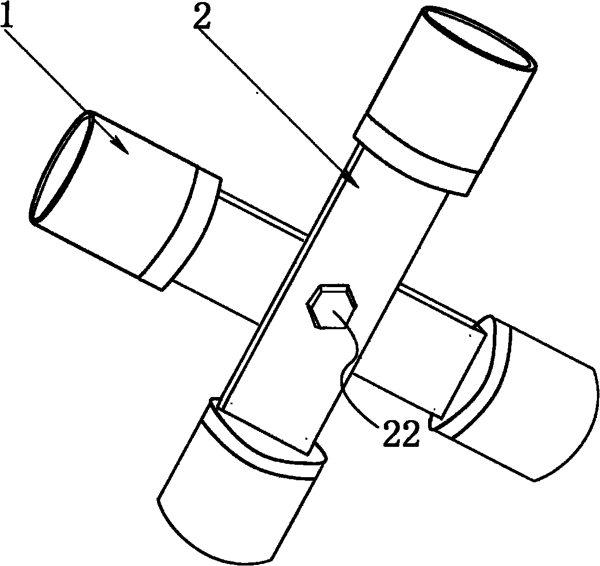
[0020] like Figure 4 As shown, the structure is basically similar to that described in the specific embodiment 1, but the difference is image 3 The connecting handle 2 of the steel pipe connector is two pieces, not one piece in the specific embodiment 1. When it is designed as two pieces, when it is connected with other connecting pieces 3, other connecting pieces 3 can be clamped. Bolt holes 21 are all provided on the two connecting handles, and the positions of the bolt holes 21 on the two connecting handles 2 are designed correspondingly.

specific Embodiment 3

[0021] like Figure 5 As shown, the structure and design are basically similar to the steel pipe joint in embodiment 1, the difference is that instead of one bolt hole 21 being provided on the connecting handle 2, multiple bolt holes 21 are provided on the connecting handle 2 . According to the needs of other connectors 3 of different materials, it is possible that a bolt hole 21 cannot play a good fixing role at all.

specific Embodiment 4

[0022] like Image 6 As shown, the structure and design are similar to the steel pipe connector described in Embodiment 3, except that the connecting handle 2 is designed in two pieces for clamping other connectors. And the bolt holes 21 on the two connecting handles 2 are designed to be corresponding, so that the connecting handle 2 can be connected with other connecting parts 3 by bolts 21 .


PUM


Abstract

The invention relates to a steel pipe connector for a steel structure in the building industry, in particular to a welding spot-free steel pipe connector. The invention provides the steel pipe connector; and a sleeve and a connecting handle are connected not through the welding technology, so the firmness is improved, the manufacturing process is reduced, and the appearance is more attractive. The steel pipe connector comprises the sleeve, the connecting handle integrated into a whole with the sleeve, and a duck tongue-shaped slope arranged between the connecting handle and the sleeve. The sleeve and the connecting handle are integrated into a whole, so the problems in the prior art are radically solved, and the welding and detection are not needed. The duck tongue-shaped slope ensures natural transition between the connecting handle and the sleeve; and the integral appearance is agreeable.

Description

technical field [0001] The invention relates to a steel pipe connection head of a steel structure in the construction industry, in particular to a steel pipe connection head without welding spots. Background technique [0002] At present, the commonly used joint forms of steel pipe frame structures in building structure construction mainly include ordinary steel pipe frame joints, Andegu steel pipe frame joints, grid structure joints and other structural forms. Among them, ordinary steel pipe frame nodes mainly include fastener type steel pipe frame and bowl buckle type steel pipe frame. There are three basic types of fastener-type steel pipe frame connection nodes: right-angle fasteners, rotary fasteners and butt fasteners. The right-angle fastener is used for the vertical cross connection of two steel pipes; the rotary fastener is used for the cross connection of two steel pipes at any angle; the butt fastener is used for the butt connection of two steel pipes. The grid ...

Claims


Application Information

Patent Timeline
Patent Type & Authority Applications(China)
IPC IPC(8): E04B1/58
Inventor 魏磊
Owner 上海珊迪建筑科技有限公司
Why Eureka
Try Eureka