Systems and methods for real-time monitoring of die use or yield

A technology for productivity and monitoring systems, used in general control systems, control/regulation systems, home appliances, etc.

Inactive Publication Date: 2011-03-02
ONTARIO DIE INT
View PDF0 Cites 9 Cited by
  • Summary
  • Abstract
  • Description
  • Claims
  • Application Information

AI Technical Summary

Problems solved by technology

However, the worker must end up with the correct number of pieces cut for each pattern to satisfy a particular order

Method used


Image

  • Systems and methods for real-time monitoring of die use or yield
  • Systems and methods for real-time monitoring of die use or yield
  • Systems and methods for real-time monitoring of die use or yield

Examples


Embodiment Construction

[0068] This application includes by reference the entire contents of PCT / CA2007 / 001474 filed on August 28, 2007, entitled "SYSTEMS OR METHOD FOR TRACKING DIE USE OR YIELD".

[0069] The following description will provide examples of systems and methods for real-time monitoring of mold usage or throughput rates. However, in this document, one or more inventions that do not appear in the claims may be disclosed in the following description, and the claims in this document may not represent each device or method described below. Each part of any particular device or method. The content not required by the inventor and its assignee in this application does not mean abandoning any of the above inventions or contributing them to the public.

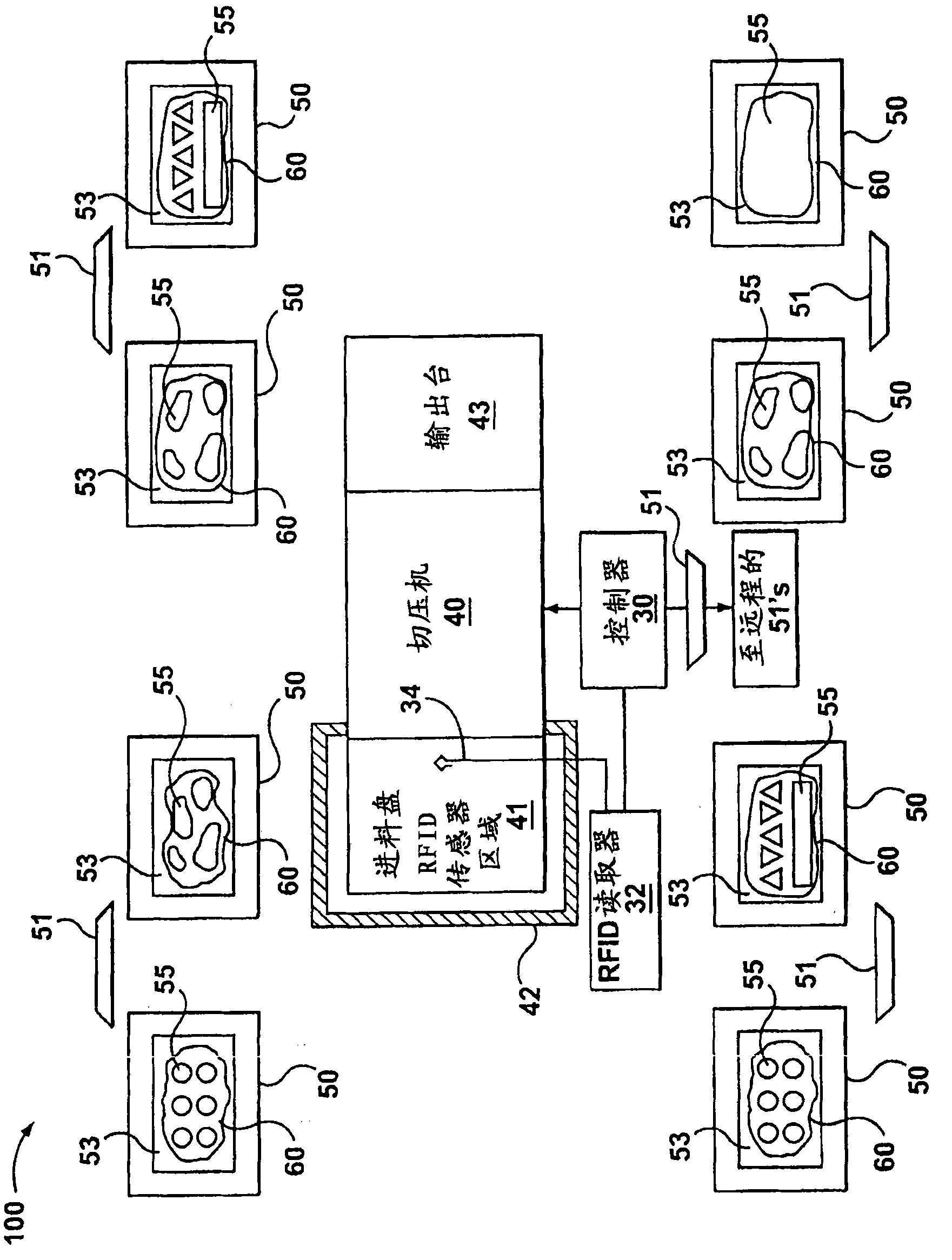
[0070] figure 1 A schematic diagram of a system 100 according to an example is shown. The system 100 generally includes a controller 30, a cutting press 40, a number of work stations 50 (optionally referred to as a nesting unit or an arrangement s...


PUM


Abstract

A method for monitoring die cutting comprising the steps of placing at least one cutting die on a hide, each cutting die having a particular pattern and an RFID (Radio Frequency Identification) tag coupled thereto, each RFID tag containing die-related information about that particular cutting die, repeatedly reading at least one RFID tag to obtain the die-related information for each RFID tag in real-time, based on the die-related information, determining whether the hide is ready for cutting, generating an output based on with whether the hide is ready for cutting, and when the hide is ready for cutting, cutting the hide.

Description

[0001] Related application [0002] This application claims the benefit of U.S. Provisional Patent Application Serial No. 61 / 032,320 filed on February 28, 2008, entitled "SYSTEMS AND METHODS FOR REAL TIME TRACKING OF DIE USE OR YIELD", the entire contents of which are incorporated herein by reference. Technical field [0003] The invention relates to the field of mold cutting. Background technique [0004] The following paragraphs are not an admission that any content discussed therein can be cited as prior art or as common knowledge of those skilled in the art. [0005] Leather products, such as automotive interior parts (such as car seats), can be made from leather sheets cut into patterns. In order to cut the leather sheet, a mold or cavity can be formed into the shape of the pattern, placed on the leather, and cut through the leather by a cutting press. Several mold shapes may be required to cut various pieces, which will be stitched together to form the final product. For a gi...

Claims


Application Information

Patent Timeline
Patent Type & Authority Applications(China)
IPC IPC(8): B26F1/38B26D7/28B26F1/44B68F1/00G05B23/02G06K7/10
CPCG06Q10/043G05B2219/37256B26D5/34G05B19/4065B26F1/46C14B5/02G05B2219/45137B26F1/40Y10T83/04Y10T83/141
Inventor G·S·莱文
Owner ONTARIO DIE INT
Why Eureka
Try Eureka