Device for electrophotographic printing or copying

A technology of electrophotography and hot air, applied in the direction of electric recording process applying charge pattern, equipment for applying electric recording process of charge pattern, electric recording technique, etc., to achieve the effect of high heat transfer, good adjustment or change

Inactive Publication Date: 2013-02-06
HEIDELBERGER DRUCKMASCHINEN AG
View PDF5 Cites 0 Cited by
  • Summary
  • Abstract
  • Description
  • Claims
  • Application Information

AI Technical Summary

Problems solved by technology

Although this provides very good results, it has the disadvantage that the heating of the printed image is different when printing in color

Method used


Image

  • Device for electrophotographic printing or copying

Examples


Embodiment Construction

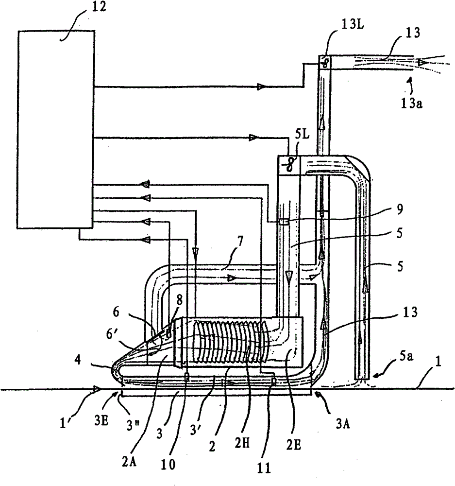
[0027] As can be seen from the figure, a wall 3 ′ made of sheet metal is arranged above a medium in the form of a metal foil 1 on which a printed image made of ink is arranged. The wall 3' is part of a rectangular channel or shaft 3 through which the metal foil 1 is guided. The shaft 3 extends in the conveying direction of the metal foil 1 described by the arrow 1 ′. The end faces of the shaft 3 are closed by means of plates 3 ″, each of which has a slot through which the foil is guided into the shaft 3 or out of the shaft 3 .

[0028] In addition, a slit nozzle 4 is provided at the inlet 3E of the shaft 3 , upstream of the outlet 3A of the shaft 3 in the conveying direction 1 ′ of the foil 1 , the width of which slot nozzle 4 is equal to the width of the shaft 3 . The slot nozzle 4 is connected on the inlet side to the outlet 2A of the hot air blower 2 . An electrically operable heating coil in the form of an electric heater 2H is arranged in the hot air blower 2 . Air can...


PUM


Abstract

A device for electrophotographic printing or copying, in which toner in keeping with an object to be printed or copied can be applied onto a medium 1 and fixed on the medium 1 by means of heat, is characterized in that a hot air fan 2 is present, by means of which heated air can be applied onto the medium 1 provided with toner, wherein the hot air fan 2 comprises an inlet 2E, by means of which air can be supplied to the hot air fan 2, and an outlet 2A, by means of which air heated by the hot air fan 2 can be delivered.

Description

technical field [0001] The invention relates to a device for electrophotographic printing or copying according to the preamble of claim 1, wherein ink can be applied to a medium according to the object to be printed or copied and can be fixed on the medium by means of heat Above, the device has a hot air blower by means of which heated air can be applied to the medium provided with the ink. Background technique [0002] Such a device is known, for example, from DE 26 13 066 A1. In this known device, the air heated by the heating device is guided along the medium provided with the ink. For this purpose, a ventilation device is provided which blows the air heated by the heating device along the medium provided with the ink. The heating means and the ventilation means are arranged in an inherently closed channel which has a straight section through which the medium provided with ink is guided. [0003] Because there is a closed air circulation through the closed channel, al...

Claims


Application Information

Patent Timeline
Patent Type & Authority Patents(China)
IPC IPC(8): G03G15/20
CPCG03G15/2003
Inventor 汉斯·玛西亚
Owner HEIDELBERGER DRUCKMASCHINEN AG
Why Eureka
Try Eureka