SCR (silicon controlled rectifier) denitration reactor of coal fuel gas

A denitration reactor, coal-fired flue gas technology, applied in chemical instruments and methods, dispersed particle separation, separation methods, etc., can solve the problems of mixing uniformity, increase system pressure drop, shorten mixing distance, etc., to achieve good ammonia nitrogen Mixing effect, reducing adjustment difficulty, reducing the effect of the number of ammonia injection pipes

Inactive Publication Date: 2011-03-23
GUANGZHOU INST OF ENERGY CONVERSION - CHINESE ACAD OF SCI
View PDF3 Cites 18 Cited by
  • Summary
  • Abstract
  • Description
  • Claims
  • Application Information

AI Technical Summary

Problems solved by technology

However, since the denitrification efficiency of the flue gas denitrification device is greatly affected by the uniformity of the flue gas flow velocity distribution and the mixing uniformity of the reducing agent ammonia / nitrogen oxides, if the flow velocity distribution is uneven or the ammonia / nitrogen oxides are not mixed uniformly, the Greatly reduce the denitrification efficiency, or cause ash blocking, and even cause the boiler to trip and shut down, which will have a negative impact on the safe operation of the power plant and cause economic losses
[0003] At present, in commercial application, the ammonia injection device in the form of a grid is generally used. The ammonia injection grid method adopts multi-point injection zone adjustment. Due to the large number of reductant ammonia injection pipes and nozzle holes, it makes its It is quite difficult to adjust in actual operation. The static mixer that must be installed in order to improve the mixing effect and shorten the mixing distance often increases the installation cost and increases the pressure drop of the system and does not reduce the adjustment difficulty of ammonia injection during operation.

Method used


Image

  • SCR (silicon controlled rectifier) denitration reactor of coal fuel gas
  • SCR (silicon controlled rectifier) denitration reactor of coal fuel gas
  • SCR (silicon controlled rectifier) denitration reactor of coal fuel gas

Examples


Embodiment

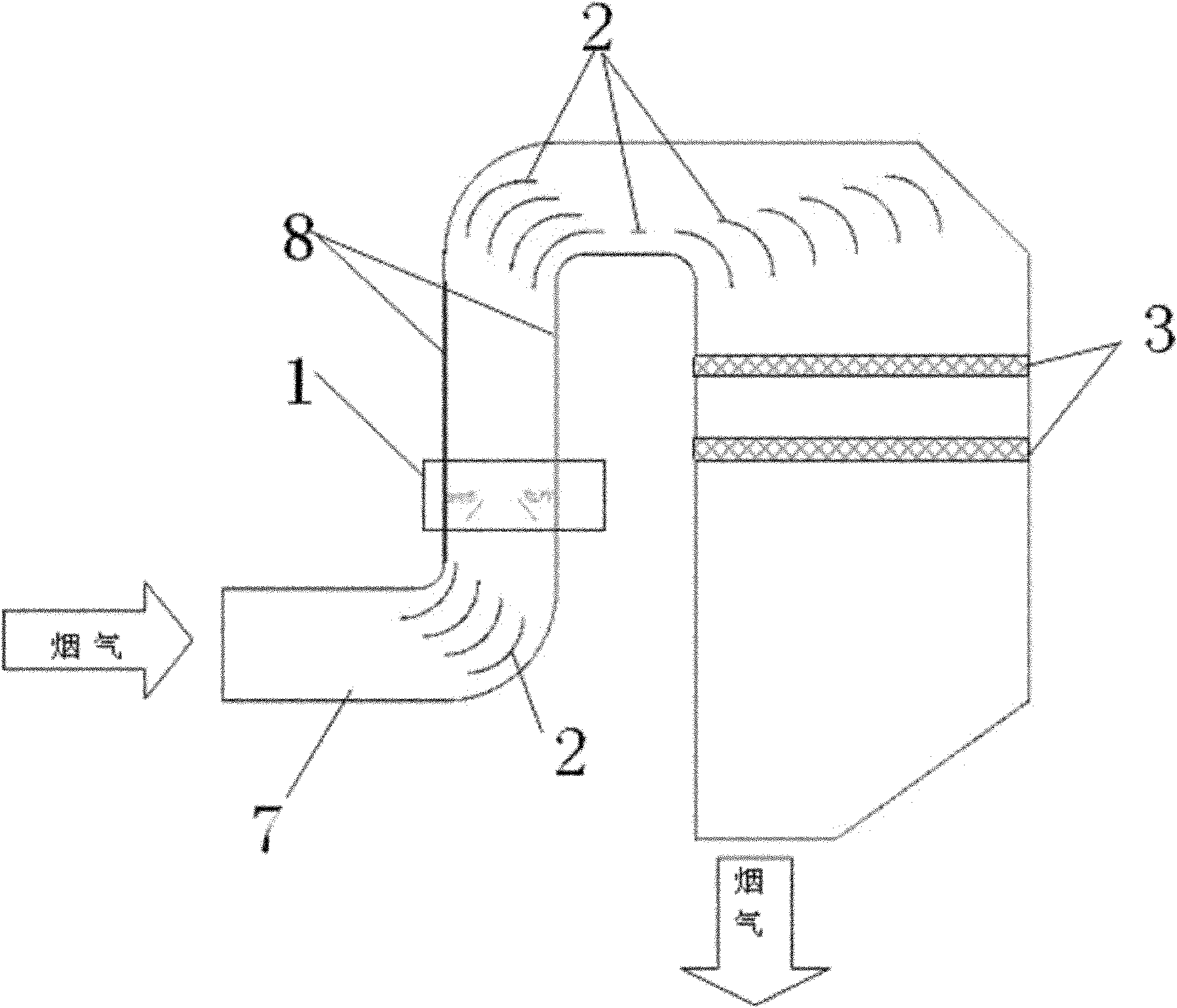
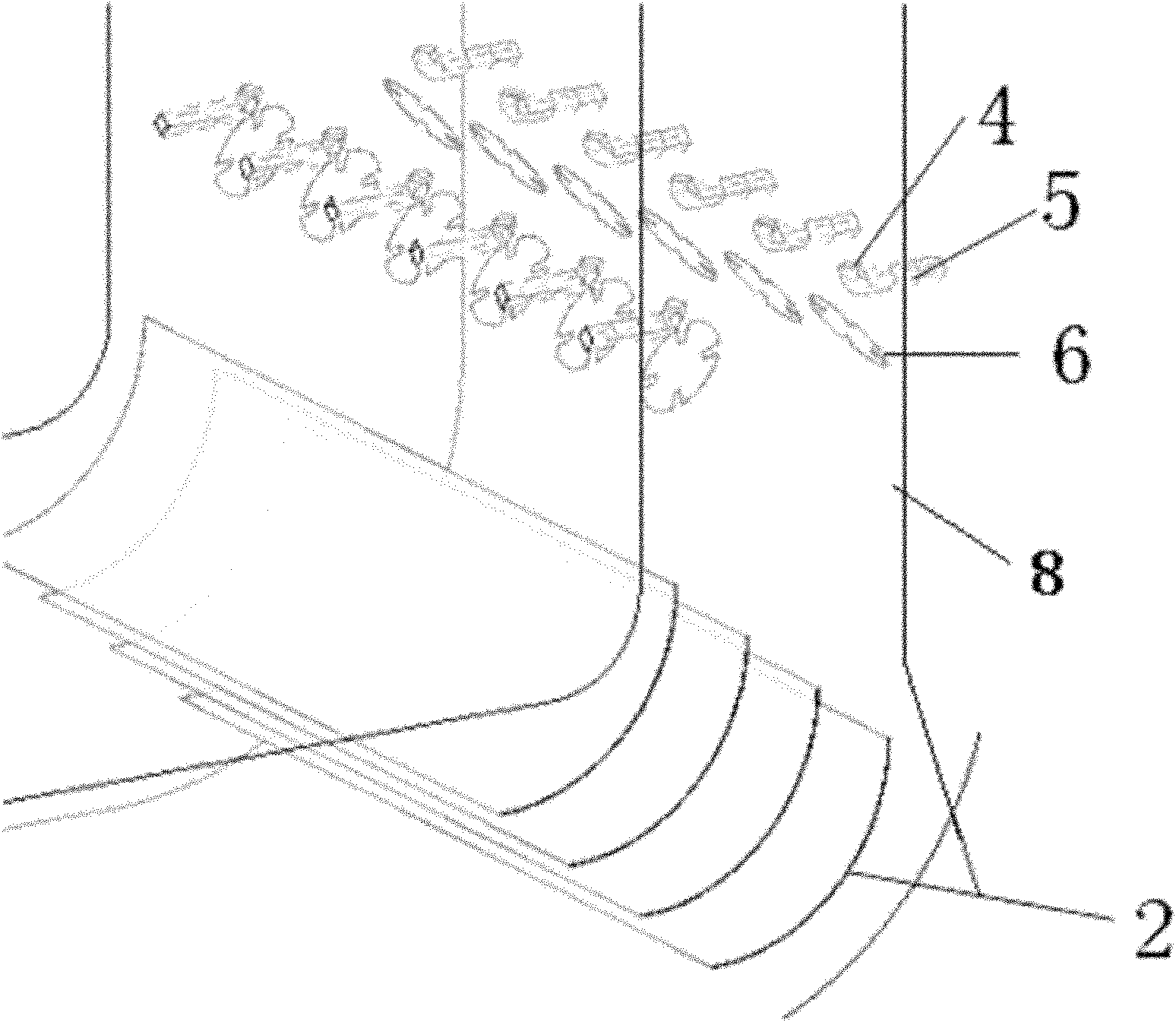
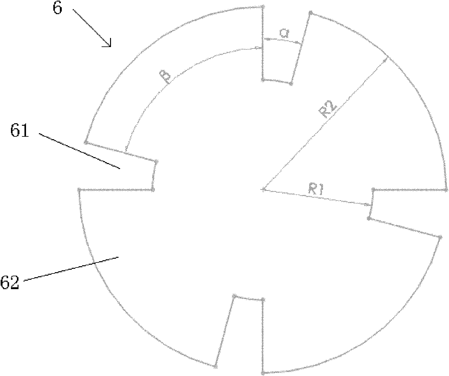
[0017] see figure 1 , figure 2 and Figure 4 As shown, a coal-fired flue gas SCR denitrification reactor includes a flue 7, a deflector 2 is provided at the corner of the flue 7, and a deflector 2 is provided in the flue 7 near the upper corner of the flue gas inlet. The strong vortex spray ammonia mixing device 1, the strong vortex spray ammonia mixing device 1 includes six to thirty reductant ammonia injection pipes 4, and ammonia nozzles 5 arranged at the ends of the reductant ammonia injection pipes 4, the reductant ammonia injection pipes The pipe 4 is symmetrically arranged on both sides of the flue 7, and the reducing agent ammonia is sprayed from the nozzle at the end of the injection pipe, and the injection direction is consistent with the direction of the flue gas flow; at the upstream of each reducing agent ammonia injection pipe 4, there is a Strong vortex generator 6, strong vortex generator 6 is fixedly connected with flue inner wall by support beam, each stro...


PUM


Abstract

The invention discloses an SCR (silicon controlled rectifier) denitration reactor of coal fuel gas, which comprises a flue. A high swirl ammonia injection mixer is arranged in the flue adjacent to the upper side of a flue gas inlet corner. The high swirl ammonia injection mixer comprises a plurality of reducer ammonia injection pipes and ammonia nozzles arranged at the ends of the reducer ammonia injection pipes. The reducer ammonia injection pipes are symmetrically arranged on both sides of the flue. The direction in which a reducer is injected by the ammonia nozzles is in accordance with coming direction of the flue gas. High swirl generators connected to the inner wall of the flue are arranged opposite to the upstream of the reducer ammonia injection pipes. Each high swirl generator forms an angle of 20-70 degrees with the inner wall of the flue. Because of the special structure of the high swirl generator, after surrounding the high swirl generator, the flue gas forms large intensity stable swirl in the flowing direction so that the flue gas can entrain the reducer in a long distance downstream. According to the result of CFD (Computational Fluid Dynamics) numerical simulation, at different flue gas flowing speeds, the device can achieve good ammonia nitrogen mixing effect.

Description

technical field [0001] The invention relates to the technical field of coal-fired flue gas SCR denitrification reactors, in particular to an ammonia injection mixing device for coal-fired flue gas SCR denitrification reactors. Background technique [0002] The boiler SCR flue gas denitrification device of a thermal power plant has the function of removing the pollutant nitrogen oxides (NOx) in the flue gas, so as to meet the emission standards of the pollutants in the flue gas of the power plant. However, since the denitrification efficiency of the flue gas denitrification device is greatly affected by the uniformity of the flue gas flow velocity distribution and the mixing uniformity of the reducing agent ammonia gas / nitrogen oxides, if the flow velocity distribution is uneven or the mixing of ammonia gas / nitrogen oxides is uneven, the It will greatly reduce the denitrification efficiency, or cause ash blocking, and even cause the boiler to trip and shut down, which will ha...

Claims


Application Information

Patent Timeline
Patent Type & Authority Applications(China)
IPC IPC(8): B01D53/90B01D53/56
Inventor 冯自平宋文吉陈金发罗俊杰王在华
Owner GUANGZHOU INST OF ENERGY CONVERSION - CHINESE ACAD OF SCI
Why Eureka
Try Eureka