Driving shaft of electric switch

A technology for electrical switches and drive shafts, applied in switch lubrication, contact drive mechanism, contact vibration/shock damping, etc., and can solve problems such as non-installation of torsion springs

Inactive Publication Date: 2013-03-20
SIEMENS AG
View PDF1 Cites 0 Cited by
  • Summary
  • Abstract
  • Description
  • Claims
  • Application Information

AI Technical Summary

Problems solved by technology

The device installs a torsion spring between the driving gear and the sliding mechanism, and the two ends of the torsion spring are fixed. Its function is to keep the relative position of the main spring and the gear stable, but the torsion spring is not installed on the drive shaft.

Method used


Image

  • Driving shaft of electric switch
  • Driving shaft of electric switch
  • Driving shaft of electric switch

Examples


Embodiment Construction

[0022] In order to have a clearer understanding of the technical features, purposes and effects of the present invention, the specific embodiments of the present invention will now be described with reference to the accompanying drawings. The equi-orientation relationship only refers to the relative positional relationship of the components shown in the drawings, and does not represent their absolute position.

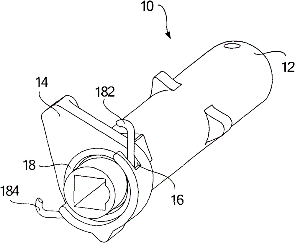
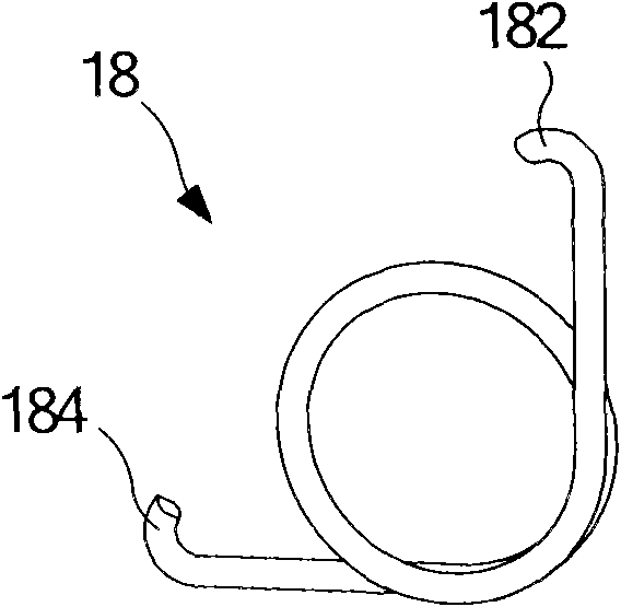
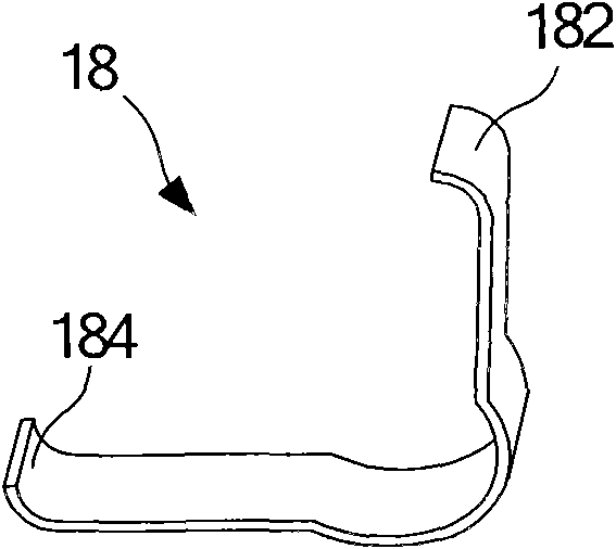
[0023] Such as figure 1 As shown, the drive shaft 10 has a shaft body 12 and a cam portion 14 located at the lower end of the shaft body 12. The cam portion 14 has a slot 16 perpendicular to the shaft body 12 and along the circumference of the cam portion 14. The spring 18 sleeved in the socket 16. The spring 18 has two ends protruding from the slot 16, one is the closing end 182 corresponding to the closing position of the drive shaft 10, and the other is the opening end 182 corresponding to the opening position of the drive shaft 10. Gate terminal 184 .

[0024] ...


PUM


Abstract

The shaft (10) has a groove (16) running transverse to a longitudinal axis of a shaft body (12) and formed at a cam wheel part (14). Two ends (182, 184) of a spring (18) e.g. torsional spring and locking ring, are protruded into the groove. One of the ends of the spring rests at a sliding part in a closed condition while the other end is not in contact with the sliding part. The latter end of the spring rests at the sliding part in an opening condition when the former end is not in contact with the sliding part. The ends of the spring include a curved part.

Description

technical field [0001] The invention relates to a drive shaft of an electric switch, in particular to an electric switch drive shaft with a spring installed at one end. Background technique [0002] Electrical switches are usually used in power systems to interrupt the current by separating the matching electrical contacts, so as to protect the system, loads and users, and avoid electrical faults and malfunctions. Usually, the separation and re-closing of electrical contacts are accomplished by means of appropriate power mechanisms. At present, the opening and closing operation of electrical switches mainly relies on the main spring as the driving force to push the drive shaft to the closing or opening position. When the operator manipulates the switch to close and open, it will bear a large impact load . [0003] US Patent No. 5861784 discloses a manual override mechanism for electrical switches. This device has installed a torsion spring between driving gear and sliding...

Claims


Application Information

Patent Timeline
Patent Type & Authority Patents(China)
IPC IPC(8): H01H3/60
CPCH01H3/62H01H3/42
Inventor 陈德州
Owner SIEMENS AG
Why Eureka
Try Eureka