Reaction rod arrangement

A rod device, technology of reaction, applied in the direction of transportation and packaging, cantilevers mounted on pivots, rigid supports for bearing components, etc.

Active Publication Date: 2013-04-10
孔斯贝格汽车公司
View PDF5 Cites 0 Cited by
  • Summary
  • Abstract
  • Description
  • Claims
  • Application Information

AI Technical Summary

Problems solved by technology

[0007] Another problem is that the elastomer has a high risk of displacement along the longitudinal axis relative to the inner metal body

Method used


Image

  • Reaction rod arrangement
  • Reaction rod arrangement
  • Reaction rod arrangement

Examples


Embodiment Construction

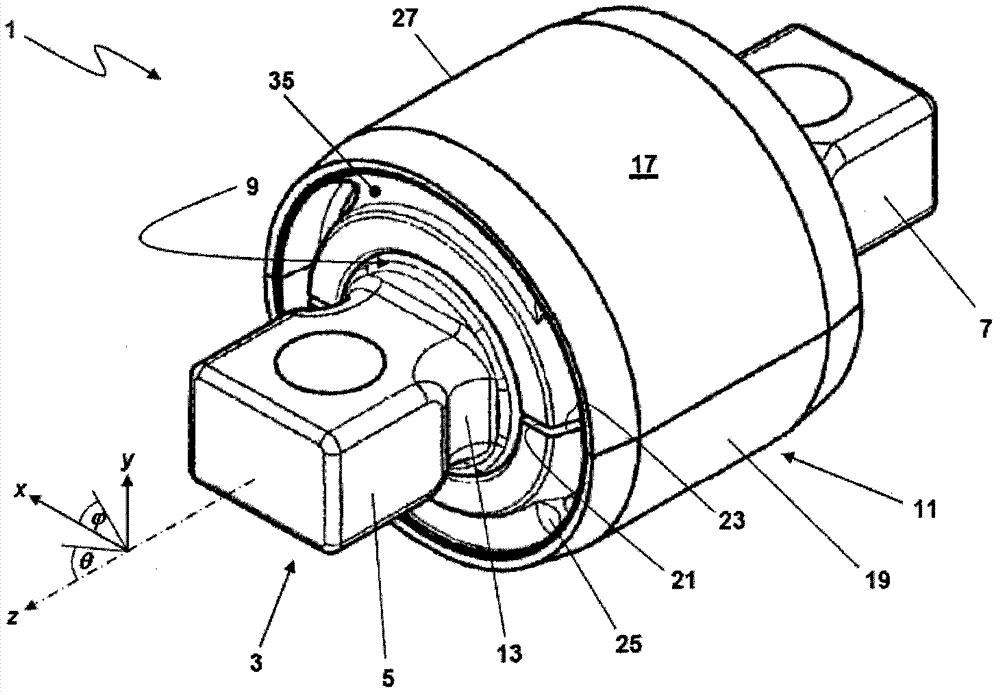
[0025] figure 1 The perspective view of the figure shows a preferred embodiment of the bushing 1 of the invention. A central rigid core part 3 defines the longitudinal axis z. The rigid core part 3 basically comprises three main parts along the longitudinal axis z. The two axial outer fitting parts 5, 7 are each suitably fixed on the vehicle part, and on the axial middle bearing part 9 surrounded by the elastomer 11, so that in figure 1 is basically hidden.

[0026] To clarify the different directions of motion, define a such as figure 1 The coordinate system shown is useful. Starting with a Cartesian coordinate system with a z-axis corresponding to the longitudinal axis of the rigid core part 3 and a cross-section covered by the vertical axes x and y, spherical coordinates such as azimuth can be defined and polar angle θ. Azimuth represents rotation about the longitudinal axis z, while tilt in the tilt direction shown by is represented by rotation of the polar angle...


PUM


Abstract

The present invention refers to a reaction rod arrangement for a vehicle including a bushing. The bushing comprises a rigid core member having a bearing portion and defining a longitudinal axis. An elastomer body is arranged on at least a portion of a radially outer surface of the bearing portion. The bearing portion comprises a first tapering portion tapering towards one axial end of the bearing portion and a second tapering portion tapering towards an opposite axial end of the bearing portion. An axial extension of the bearing portion is larger than a maximal radial extension with respect to the longitudinal axis. The elastomer body is movably arranged on the bearing portion to perform a rotational movement about the longitudinal axis relative to the rigid core member and a tilting movement about an axis perpendicular to the longitudinal axis relative to the rigid core member.

Description

technical field [0001] The present invention relates to a reaction rod arrangement, and more particularly to a V-strut suspension for a vehicle comprising a bushing comprising a rigid core member having a bearing portion and defining a longitudinal axis, and disposed on the bearing portion elastomer on at least a portion of the radially outer surface of the Background technique [0002] Reaction rod arrangements such as V-strut suspensions can be used in automobiles for the connection between the frame and wheel suspension axles. In particular heavy vehicles such as trucks may include a V-strut suspension with both ends connected to the chassis and a central suspension point connected to the wheel suspension axle. Such a system is described, for example, in WO2005 / 080101 A1. [0003] The V-strut suspension described in WO 2005 / 080101 A1 comprises suction bushings. The suspension experiences motion in both directions of rotation and tilt, so that the V-strut suspension nee...

Claims


Application Information

Patent Timeline
Patent Type & Authority Patents(China)
IPC IPC(8): B60G7/00B60G9/00F16C11/06F16C27/06
CPCB60G2204/148F16C11/0614B60G7/005B60G2200/315B60G2206/013B60G9/022B60G2206/73B60G2204/416F16F1/393B60G2206/11B60G2204/41F16C2326/05
Inventor 斯文·波兆格加登达格芬·安徒生
Owner 孔斯贝格汽车公司
Why Eureka
Try Eureka