Folded seal retention plate with thrust surface

a technology of sealing plate and thrust surface, which is applied in the direction of fluid couplings, gearings, couplings, etc., can solve the problems of difficult insertion of sealing plates in limited torus size torque converters, and achieve the effect of preventing axial displacement of seals

Active Publication Date: 2015-09-03
SCHAEFFLER TECH AG & CO KG
View PDF2 Cites 4 Cited by
  • Summary
  • Abstract
  • Description
  • Claims
  • Application Information

AI Technical Summary

Benefits of technology

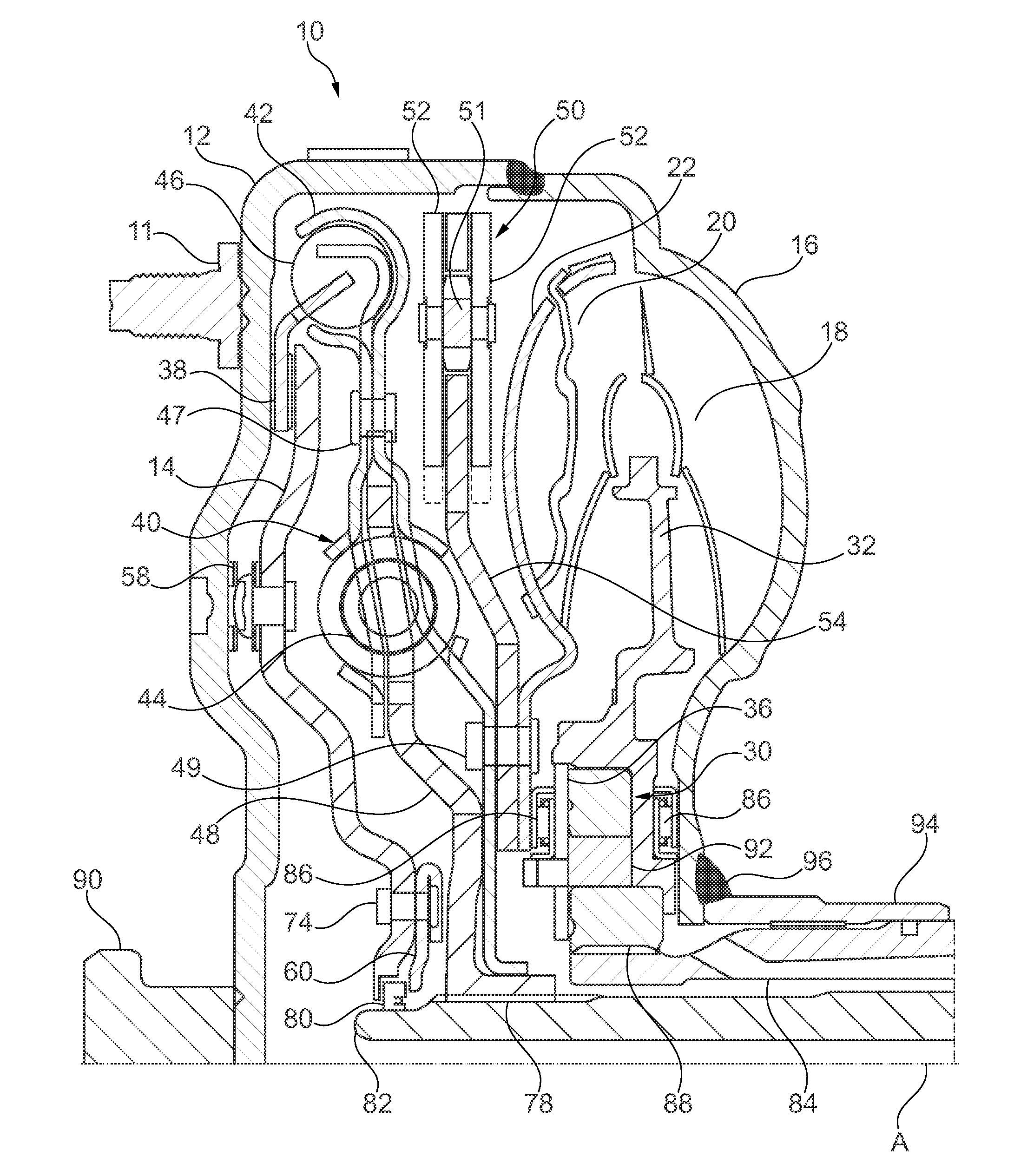
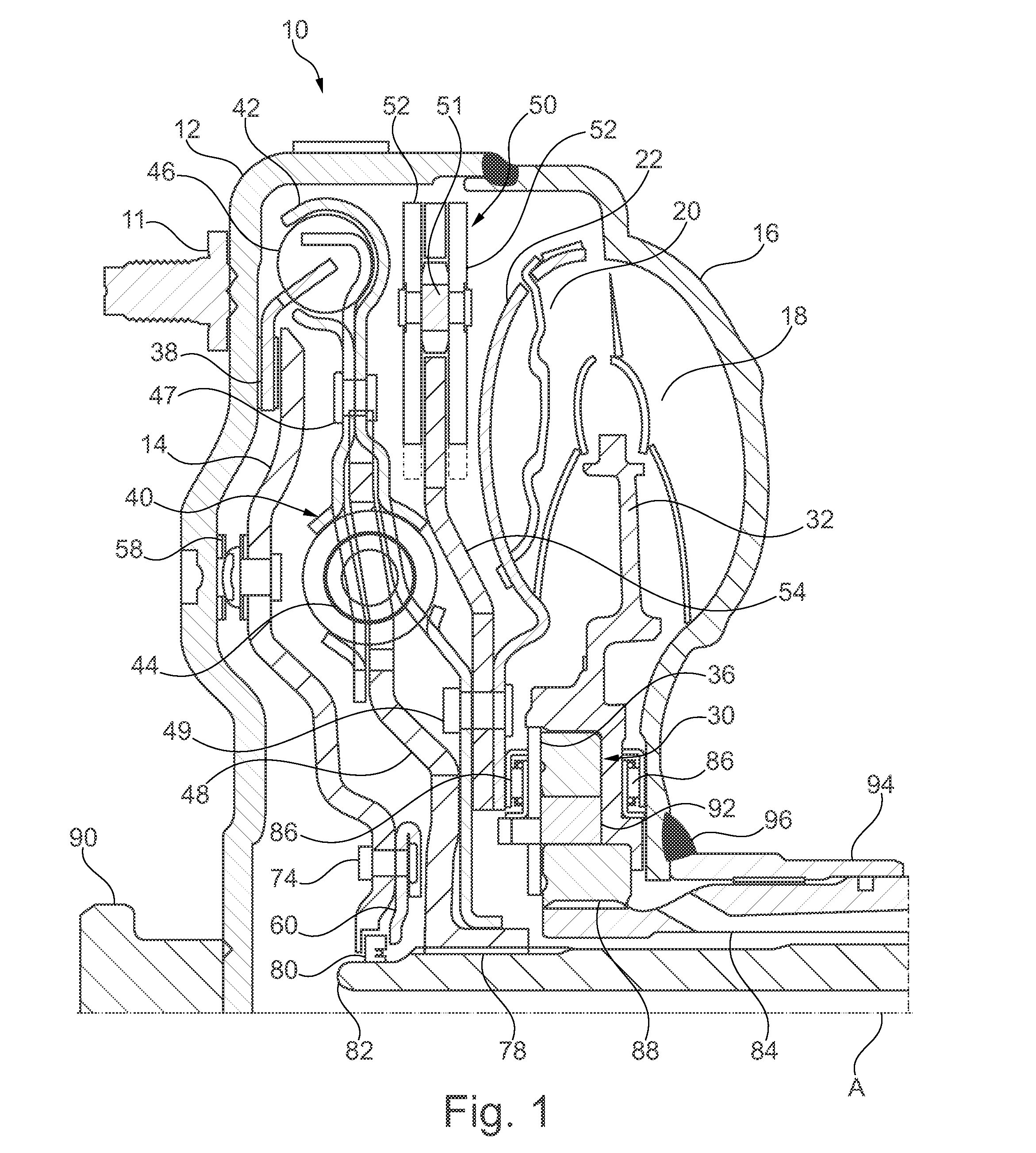
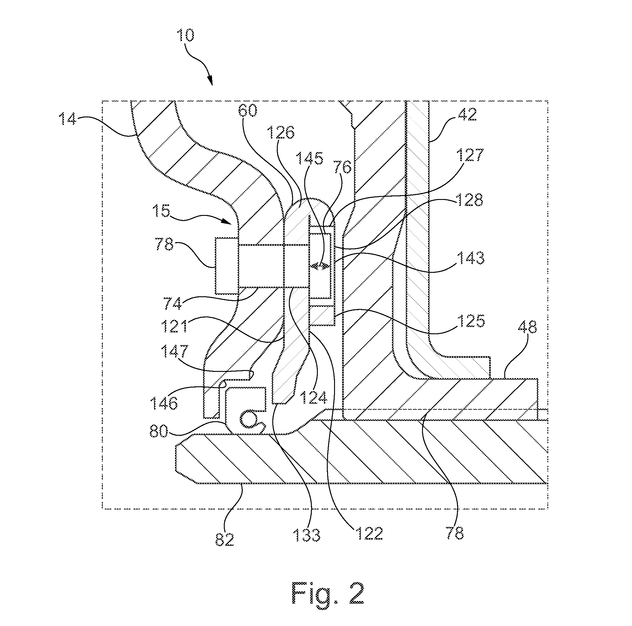
[0009]Other example aspects broadly comprise a torque converter assembly assembly comprising: a piston including a recess on a first inner radial portion; a seal retention plate having: an interior portion having a first thickness; a plurality of radially outer tabs having a second thickness extending from the interior portion, each tab having a base and radially outward tapered sides, each tab folded along the base so as to contact the interior portion and to provide a thrust portion having a total thickness; and a center opening; at least one fastener for fixedly attaching the piston to the seal retention plate; a flange facing the thrust portion; and, a seal located between the piston recess and the interior portion of the seal retention plate. In an example aspect, the seal is arranged for sealing engagement with a transmission input shaft, and where the piston is arranged to be slidably supported on the transmission input shaft. In an example aspect, the interior portion includes a first hole and the outer tab includes a second hole, where the second hole is aligned with the first hole and where the diameter of the second hole is greater than the diameter of the first hole. In an example aspect, the fastener is a rivet including a rivet head, and where the first hole is arranged for receiving the rivet and where the second hole is arranged for receiving the rivet head, and where the rivet head has a third thickness, where the third thickness is at most equal to the second thickness. In an example aspect, the seal retention plate includes scallops located on opposite sides of the outer tabs, and where the scallops extend at least partially into the interior portion. In an example aspect, the interior portion includes a first radial portion, a slant portion, and a second radial portion, and where the first radial portion and the second radial portion are arranged in parallel displacement to each other, and having the slant portion located therebetween, and where the second radial portion cooperates with the piston recess to prevent axial displacement of the seal.

Problems solved by technology

Incorporating plates for this purpose in limited torus size torque converters is difficult.

Method used


Image

  • Folded seal retention plate with thrust surface
  • Folded seal retention plate with thrust surface
  • Folded seal retention plate with thrust surface

Examples


Embodiment Construction

[0017]At the outset, it should be appreciated that like drawing numbers appearing in different drawing views identify identical, or functionally similar, structural elements. Furthermore, it is understood that this invention is not limited only to the particular embodiments, methodology, materials and modifications described herein, and as such may, of course, vary. It is also understood that the terminology used herein is for the purpose of describing particular aspects only, and is not intended to limit the scope of the present invention, which is limited only by the appended claims.

[0018]Unless defined otherwise, all technical and scientific terms used herein have the same meaning as commonly understood to one of ordinary skill in the art to which this invention belongs. Although any methods, devices or materials similar or equivalent to those described herein can be used in the practice or testing of the invention, the following example methods, devices, and materials are now de...


PUM


Abstract

A seal retention plate for a torque converter, the plate comprising: an annular body portion having a first surface; a second surface opposite the first surface; an interior portion having at least one first hole; at least one radially outer tab extending from the interior portion and folded to contact the second surface so as to provide a thrust surface; and a center opening.

Description

CROSS-REFERENCE TO RELATED APPLICATIONS[0001]This application claims the benefit under 35 U.S.C. §119(e) of U.S. Provisional Application No. 61 / 945,879, filed Feb. 28, 2014, which application is incorporated herein by reference in its entirety.FIELD[0002]The invention relates generally to a seal retention plate for a torque converter, where the seal retention plate includes a thrust surface.BACKGROUND[0003]U.S. Patent Publication No. 2014 / 0346737, hereby incorporated by reference herein, describes a piston seal assembly including a piston, plate, and seal. The piston includes a recess, wherein the seal is disposed at least partially within the recess. The plate is fastened to the piston and extends at least partially adjacent to the recess. The seal is axially movable between the piston and the plate via hydraulic fluid pressure.[0004]U.S. Patent Publication No. 2012 / 0161400, hereby incorporated by reference herein, describes a bi-directional clip seal piston.[0005]To retain a seal ...

Claims


Application Information

Patent Timeline
Patent Type & Authority Applications(United States)
IPC IPC(8): F16D25/12F16H45/02
CPCF16D25/12F16D2300/08F16H45/02F16J15/16F16H2045/0205F16H2045/0215F16H2045/0231F16H2045/0263F16H2045/0278F16D33/18F16D47/06
Inventor CERRETA, JOSHUA DAVID
Owner SCHAEFFLER TECH AG & CO KG
Why Eureka
Try Eureka