
Imaging optical system and imaging device using the same

An imaging optics and imaging technology, applied in the parts, optics, and optical components of the TV system, can solve the problems of insufficient suppression of light spots and ghosting, and achieve the effect of suppressing light spots.

Inactive Publication Date: 2011-03-23
PANASONIC CORP
View PDF3 Cites 5 Cited by
  • Summary
  • Abstract
  • Description
  • Claims
  • Application Information

AI Technical Summary

Problems solved by technology

[0010] However, even if a diaphragm or the like is provided as in Patent Documents 1 to 3, it is still impossible to sufficiently suppress the occurrence of flare and ghosting, which cause image quality deterioration, only by a general lens design.

Method used


Image

  • Imaging optical system and imaging device using the same
  • Imaging optical system and imaging device using the same
  • Imaging optical system and imaging device using the same

Examples


no. 1 approach

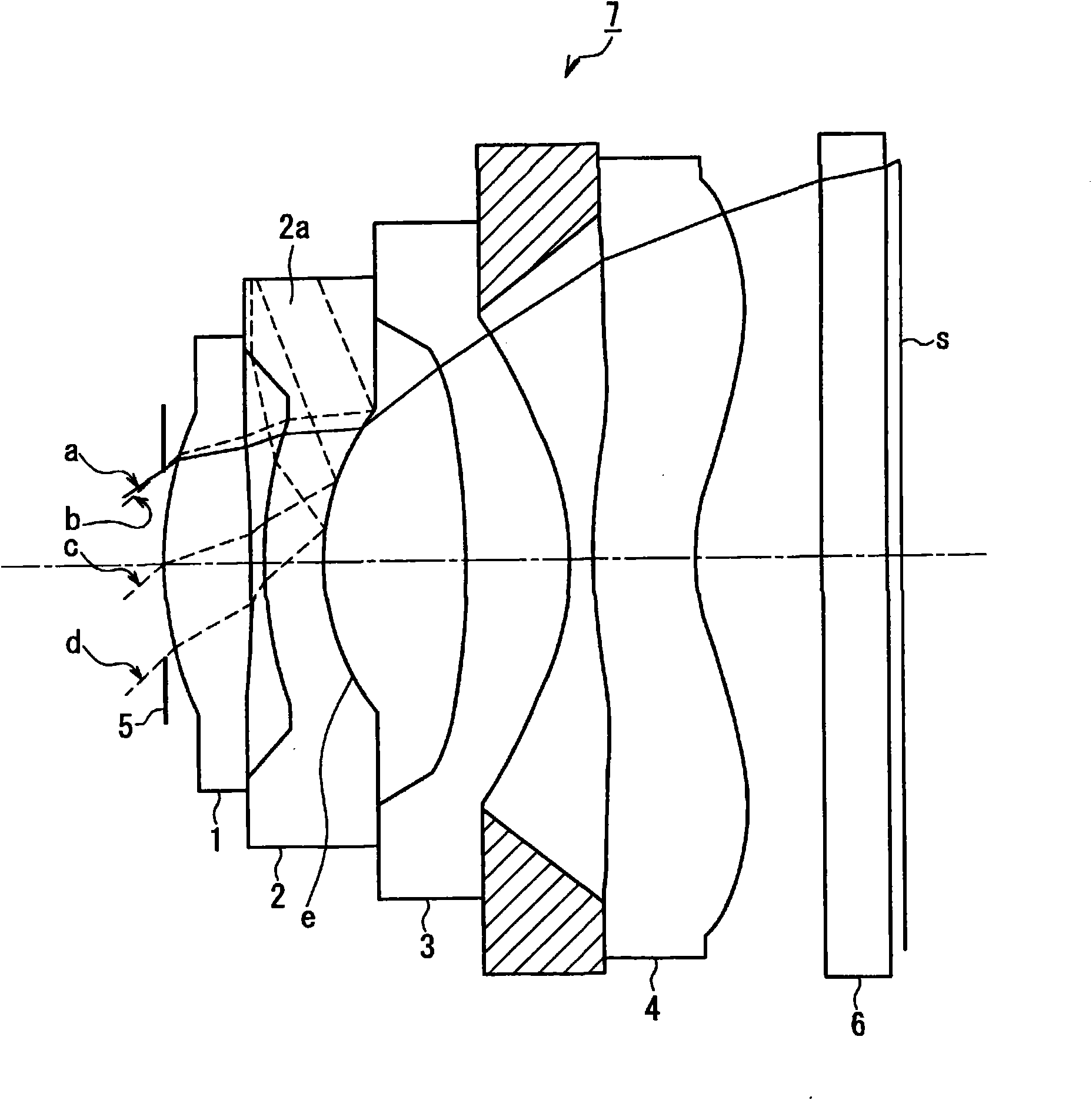
[0029] figure 1 It is a configuration diagram showing the configuration of the imaging optical system in the first embodiment of the present invention.

[0030] [1. Structure of imaging optical system]

[0031] First, the configuration of the imaging optical system of this embodiment will be described.

[0032] Such as figure 1 As shown, the imaging optical system 7 of this embodiment has figure 1 Center is the left side) toward the image plane side ( figure 1 The aperture stop 5 and the first lens 1, the second lens 2, the third lens 3, and the fourth lens 4 as optical components are arranged in sequence, and the first lens 1 has positive power. , both surfaces are convex, the second lens 2 has negative power, and is composed of a meniscus lens whose lens surface on the image side is concave, the third lens 3 has positive power, and is formed by the image side The lens surface is a convex meniscus lens, the fourth lens 4 has negative refractive power, and the lens surfac...

no. 2 approach

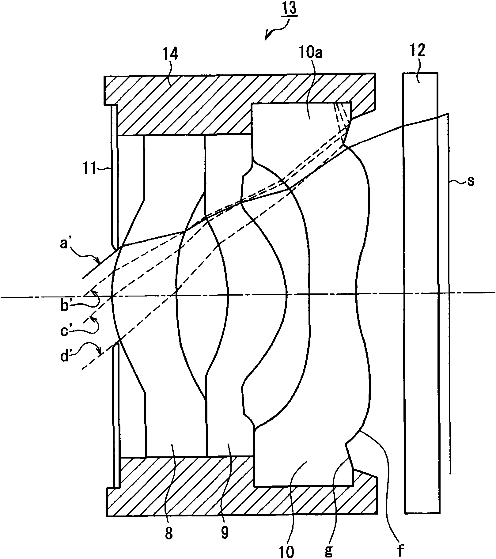
[0063] figure 2 It is a configuration diagram showing the configuration of the imaging optical system in the second embodiment of the present invention.

[0064] [1. Structure of imaging optical system]

[0065] First, the configuration of the imaging optical system of this embodiment will be described.

[0066] Such as figure 2 As shown, the imaging optical system 13 of this embodiment has figure 2 Center is the left side) toward the image plane side ( figure 2 The aperture stop 11 arranged in sequence on the right side in the middle), and the first lens 8, the second lens 9, and the third lens 10 as optical components, the first lens 8 has positive refractive power, and the lens surface on the image plane side It is a concave meniscus lens, the second lens 9 has a positive power, and the lens surface on the image side is a convex meniscus lens, the third lens 10 has a negative power, and the lens surface on the image side The surfaces are concave near the optical ax...


PUM


Abstract

Provided is an imaging optical system wherein generation of flare and ghost which cause image quality deterioration can be sufficiently suppressed. An imaging optical system (7) is provided with, in sequence from an object side to an image surface side, an aperture stop (5), a biconvex first lens (1) having a positive power as an optical member, a second lens (2) which has a negative power and iscomposed of a meniscus lens having a concave lens surface on the image surface side, a third lens (3) which has a positive power and is composed of a meniscus lens having a convex lens surface on theimage surface side, and a fourth lens (4) which has a negative power and has a concave lens surface in the vicinity of an optical axis on the image surface side. On an effective aperture section on alens surface (e) on the image surface side of the second lens (2), a total reflection surface which totally reflects incoming beams outside the angle of view is provided.

Description

technical field [0001] The present invention relates to an imaging optical system that forms an image of a subject on an imaging unit (eg, an imaging surface of an imaging element) using optical components (eg, an optical lens, a parallel plate), and an imaging device using the imaging optical system. Background technique [0002] In a conventional imaging optical system, there are unnecessary light beams (stray light) called so-called flares or ghosts that cause deterioration of image quality and do not contribute to imaging. The reason for this is that incident light outside the angle of view is reflected on the lens surface or end of the optical lens and reaches the imaging surface of the imaging element. [0003] Heretofore, the following techniques have been proposed as means for preventing deterioration of image quality caused by such flares and ghost images (see, for example, Patent Documents 1 to 3). [0004] That is, Patent Document 1 proposes an annular diaphragm ...

Claims


Application Information

Patent Timeline
Patent Type & Authority Applications(China)
IPC IPC(8): G02B13/00G02B13/18G03B11/00H04N5/225
CPCG02B27/0018H04N5/3572G02B7/022G02B9/12H04N5/2254G03B11/00G02B13/0035G02B9/34G02B13/004G02B13/18H04N23/00
Inventor 井场拓巳山下优年
Owner PANASONIC CORP
Learn More