Vehicle impact mitigation system

A vehicle collision and vehicle braking technology, which is applied in the field of vehicle collision mitigation systems, can solve high-cost and complex problems, and achieve the effect of reducing weight and saving parts cost

Inactive Publication Date: 2011-03-30
FORD GLOBAL TECH LLC
View PDF10 Cites 9 Cited by
  • Summary
  • Abstract
  • Description
  • Claims
  • Application Information

AI Technical Summary

Problems solved by technology

Although the design stiffens the front-end module in the extended position, the design uses a more costly and unnecessarily complicated method of locking the front-end module

Method used


Image

  • Vehicle impact mitigation system
  • Vehicle impact mitigation system
  • Vehicle impact mitigation system

Examples


Embodiment Construction

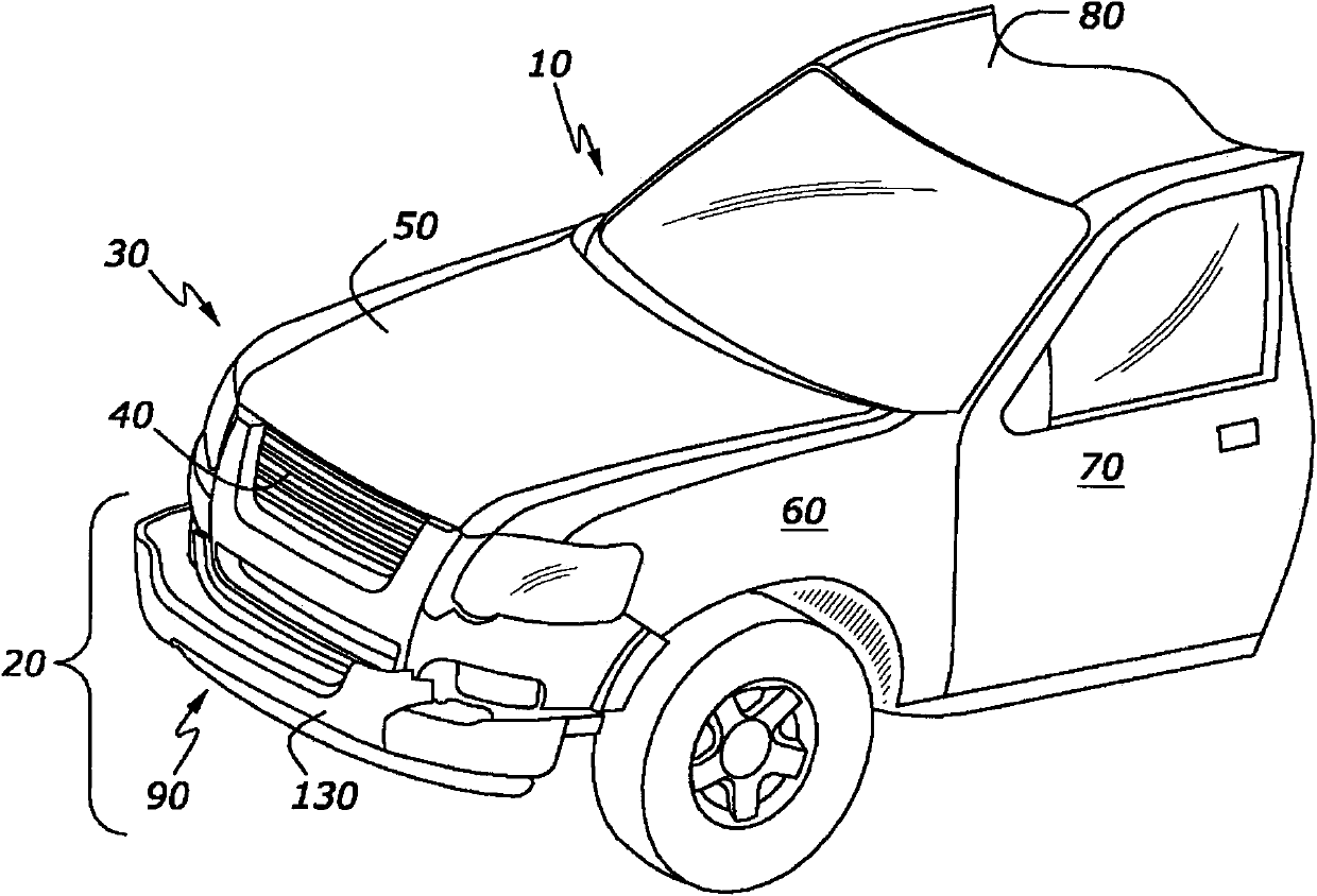
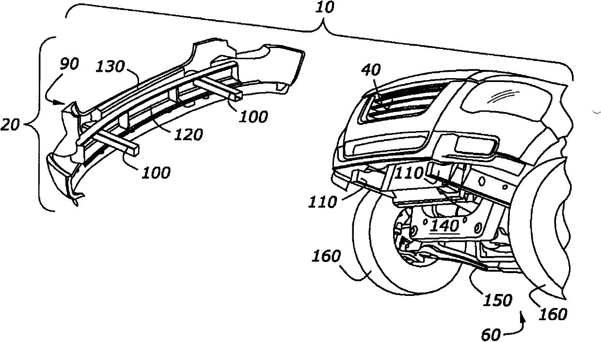
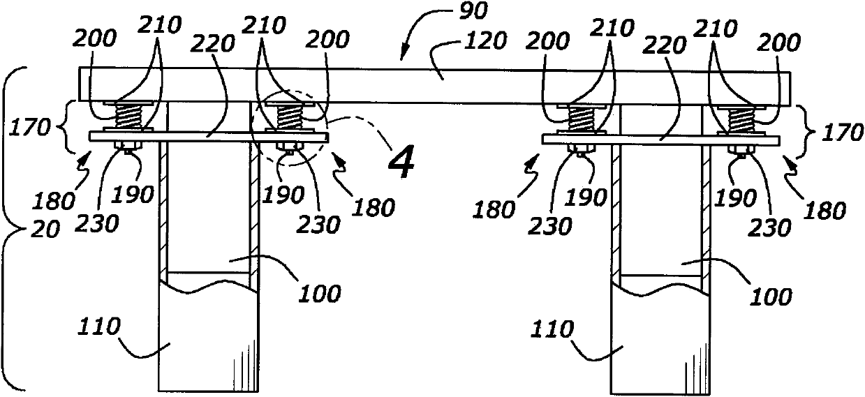
[0039] Reference attached Figure 1-19 , Where the same reference numerals represent the same or corresponding components in some views of the different illustrated vehicle collision mitigation systems. The illustrated collision mitigation system uses mechanical features to deploy the front-end modules of the vehicle. Some mechanical features, such as springs, which mount the front-end module to the vehicle, are the main propellant of the front-end module, and move the module forward or away from the vehicle. The illustrated collision mitigation system reduces the entry of vehicle components or foreign objects into the passenger compartment in a frontal collision scenario. The collision mitigation system extends or unfolds the front bumper of the vehicle and extends the main beam or side beam, thereby increasing the collision space. The increased collision space allows more collision energy to be absorbed and thereby reduces the maximum deceleration. The reduction in decelera...


PUM


Abstract

The present disclosure relates to a vehicle impact mitigation system. The impact mitigation system can be configured to mitigate front impact situations. A main rail and an extendable rail-configured to move with respect to the main rail-are provided. A front module is attached to the extendable rail and attachable to the main rail. A spring is positioned between the front module and main rail, the spring is configured to apply a force to the front module when the front module is detached from the main rail. An actuator is configured to control attachment of the front module to the main rail.

Description

Technical field [0001] The invention relates to a vehicle collision mitigation system. The vehicle module is configured to function when the vehicle is about to collide. The present invention also discusses locking mechanisms used in various collision mitigation systems. Background technique [0002] The vehicle collision mitigation system was developed to help reduce the entry of other vehicles and / or unwanted vehicle components into the passenger compartment of the vehicle during a crash. Current vehicles include front, side and top collision protection systems. A severe frontal collision situation will cause the engine and its components to enter the passenger compartment. The various designs of past collision protection systems are not as superior as the present invention. [0003] For example, the front end structure of a vehicle is generally composed of a bumper, a longitudinal beam, and an upper longitudinal beam (or "shortgun"). The stringers provide the main energy ab...

Claims


Application Information

Patent Timeline
Patent Type & Authority Applications(China)
IPC IPC(8): B60R19/18B60T7/22
CPCB60R19/34B60R19/28B60R19/40
Inventor 奥玛尔·法鲁克
Owner FORD GLOBAL TECH LLC
Why Eureka
Try Eureka