Spinning machine and yarn removing method for removing yarn remaining on yarn accumulating roller

A technology for storing rollers and yarns, applied to spinning machines, open-end spinning machines, continuous winding spinning machines, etc., can solve problems such as difficulty in effectively improving operating efficiency and restarting spinning operations

Active Publication Date: 2011-03-30
MURATA MASCH LTD
View PDF8 Cites 13 Cited by
  • Summary
  • Abstract
  • Description
  • Claims
  • Application Information

AI Technical Summary

Problems solved by technology

Therefore, it is not possible to start the spinning operation again in this state
In addition, although a method of suctioning and removing the yarn with a yarn suction device has been considered, the yarn end of the yarn may not nec

Method used


Image

  • Spinning machine and yarn removing method for removing yarn remaining on yarn accumulating roller
  • Spinning machine and yarn removing method for removing yarn remaining on yarn accumulating roller
  • Spinning machine and yarn removing method for removing yarn remaining on yarn accumulating roller

Examples


Embodiment Construction

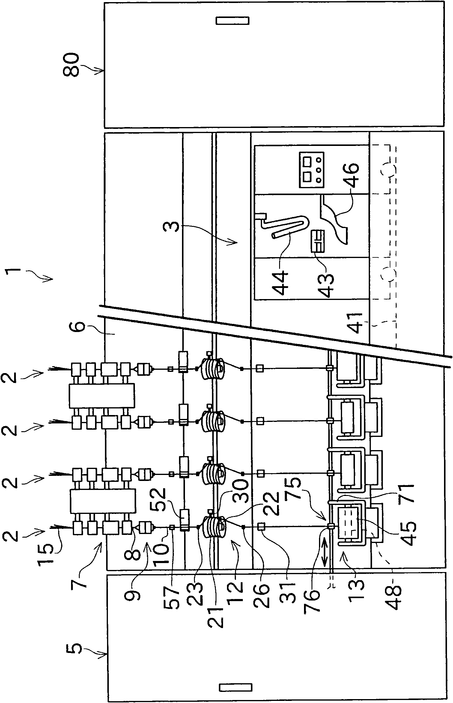
[0030] Next, a spinning frame (spinning machine) 1 according to an embodiment of the present invention will be described with reference to the drawings. In addition, in the following description, "upstream" and "downstream" mean upstream and downstream in the running direction of the yarn during spinning.

[0031] figure 1 The spinning machine 1 shown as a spinning machine includes a plurality of spindles (units) (spinning units (spinning unit) 2 ) arranged in parallel. The spinning frame 1 includes a yarn splicing cart 3 , a blower box 80 , and a motor box 5 .

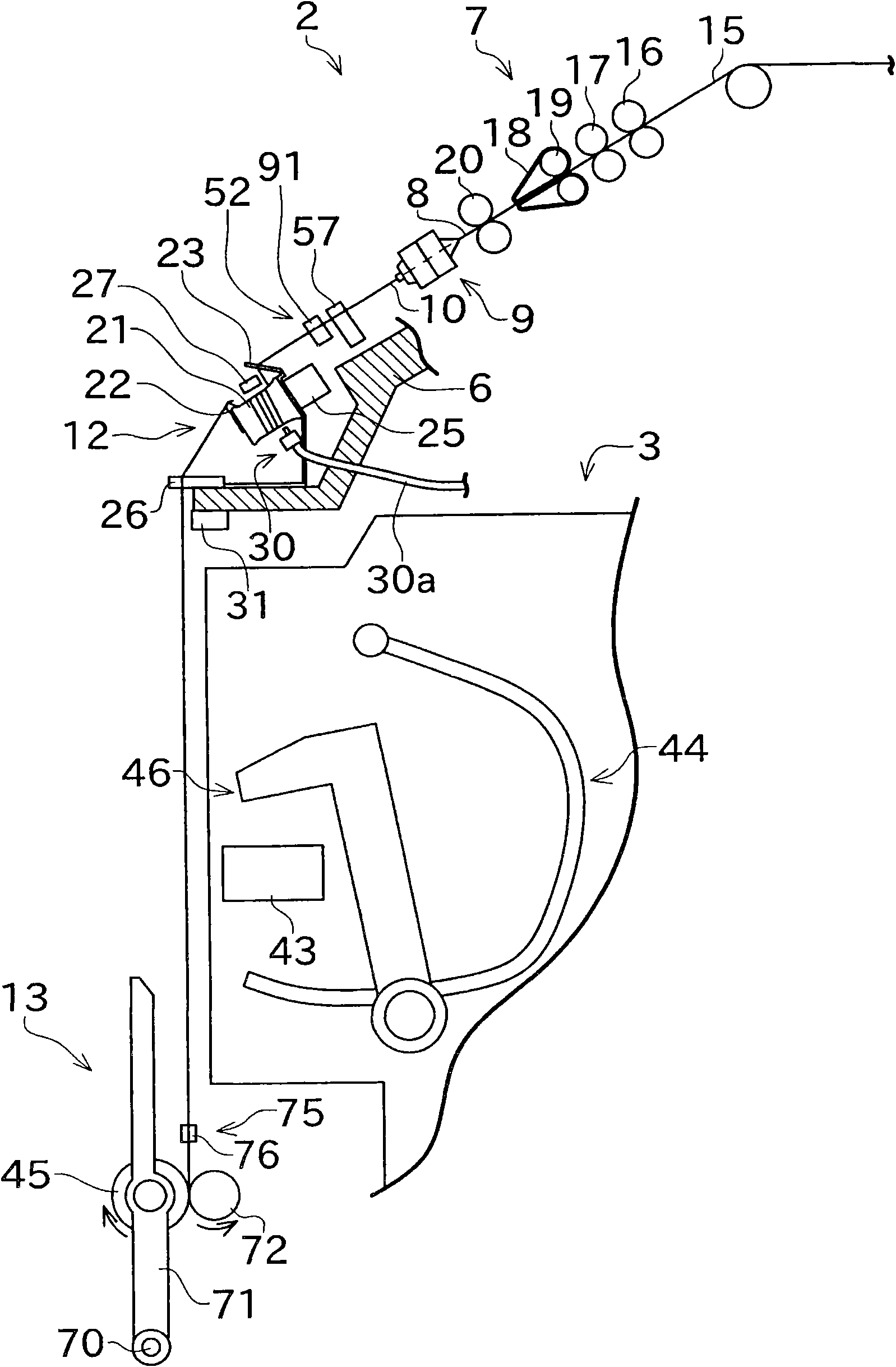
[0032] Such as figure 1 As shown, each spinning unit 2 includes a draft device (draft device) 7, a spinning device (spinning device) 9, a yarn accumulating device (yarn accumulating device) 12, and a lower thread sensor (lower thread sensor) in sequence from upstream to downstream as a main structure. - yarn sensor) 31, and winding device (winding device) 13. The draft device 7 is provided near the upper end of th...


PUM


Abstract

A spinning frame (1) includes a spinning device (9), a yarn clearer (52), a yarn accumulating roller (21), a suction opening (46), a suction device (30), and a unit controller (60). The spinning device produces spun yarn by applying twists to a fiber bundle. The yarn clearer (52) is arranged downstream of the spinning device and detects a yarn defect in the travelling spun yarn. The yarn accumulating roller (21) is arranged downstream of the yarn clearer and accumulates the spun yarn by rotating while winding the spun yarn around an outer peripheral surface thereof. The suction opening of the suction device is arranged near a base end of the yarn accumulating roller (21). The suction device (30) can generate suction airflow at the suction opening (46). The unit controller (60) delays a stoppage timing, which is a timing at which feeding of the spun yarn is stopped, when the yarn clearer (52) detects a prescribed yarn defect in which yarn strength is low, compared with when other type of yarn defect is detected, and stops the yarn accumulating roller (21) after the stoppage timing.

Description

technical field [0001] The present invention mainly relates to spinning machines provided with yarn storage rollers. Background technique [0002] Japanese Patent Laid-Open No. 11-268871 discloses a spinning device, a clearing device (yarn defect detecting device), and a local control device (controlling device). Department (control section)) spinning machinery. [0003] The yarn clearing device acquires data related to the thickness and length of the spun yarn fed from the spinning device. Based on the data, the local control device judges whether the yarn (spun yarn) at the position where the data is acquired is a yarn defect that should be cut. When the local control device determines that it is a yarn defect that should be cut, it cuts the spun yarn by an appropriate method. In addition, the spinning machine is further provided with a structure for displaying whether the thickness and length of the yarn at the part of the yarn defect that is actually cut correspond co...

Claims


Application Information

Patent Timeline
IPC IPC(8): D01H4/42D01H13/16D01H13/02
CPCB65H2701/31B65H63/06B65H51/22D01H15/00B65H67/08B65H54/88D01H4/48
Inventor 冈正毅
Owner MURATA MASCH LTD
Why Eureka
Try Eureka