Optical unit with shake correction function

a technology of optical units and functions, applied in the field of optical units with shake correction functions, can solve the problem that the module does not rotate around the optical axis

Active Publication Date: 2021-02-11
SANKYO SEIKI MFG CO LTD
View PDF0 Cites 10 Cited by
  • Summary
  • Abstract
  • Description
  • Claims
  • Application Information

AI Technical Summary

Benefits of technology

[0016]According to at least an embodiment of the present invention, the rotation support structure, which supports the movable body rotatably around the optical axis, may be supported by the gimbal structure rotatably around the first axis and the second axis. Therefore, the movable body may rotate around the rotation axis that coincides with the optical axis even when the movable body is rotating around the first axis or the second axis. The rotation support structure may include the spherical objects that roll in contact with the plate roll and the facing portion of the plate holder, and the shake-correction magnet and the rolling-correction magnet may constitute the pressurization structure that applies the force to bring the plate holder and the plate roll close to each other. Thus, the rotation support structure allows the plate roll to rotate smoothly relative to the plate holder.

Problems solved by technology

Therefore, there is a disadvantage such that, when a rolling magnetic drive structure is driven so that the movable body is rotated while the optical module is rotating around the first axis or the second axis, the optical module does not rotate around the optical axis.
With this type of rotation structure, there is a disadvantage such that the plate roll does not smoothly rotate relative to the plate holder without the application of force that causes the spherical objects to be always in contact with both the plate roll and the facing portion.

Method used


Image

  • Optical unit with shake correction function
  • Optical unit with shake correction function
  • Optical unit with shake correction function

Examples


Embodiment Construction

[0032]An optical unit with a shake correction function according to at least an embodiment of the present invention is described below with reference to the drawings.

[0033]Overall Configuration

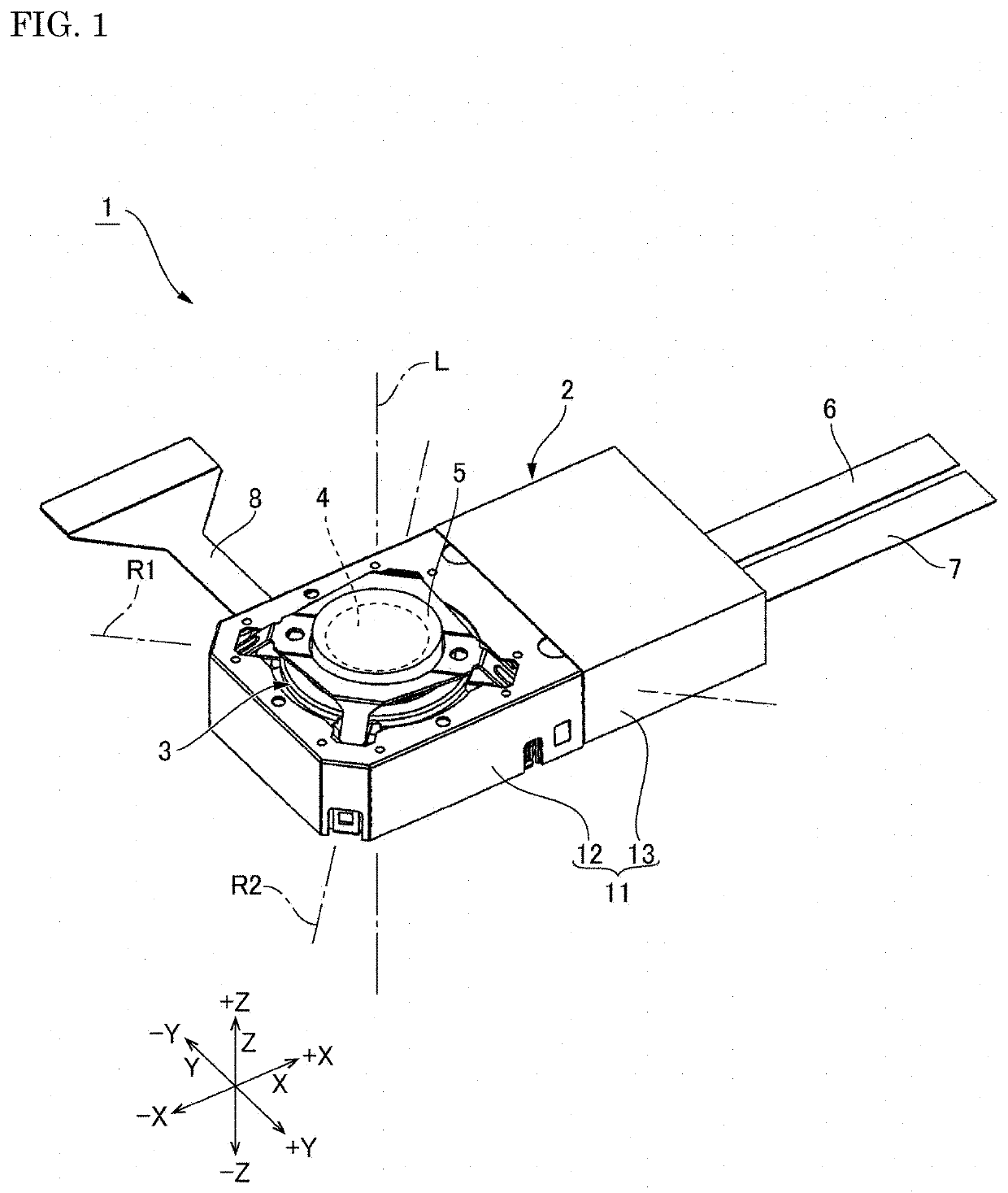
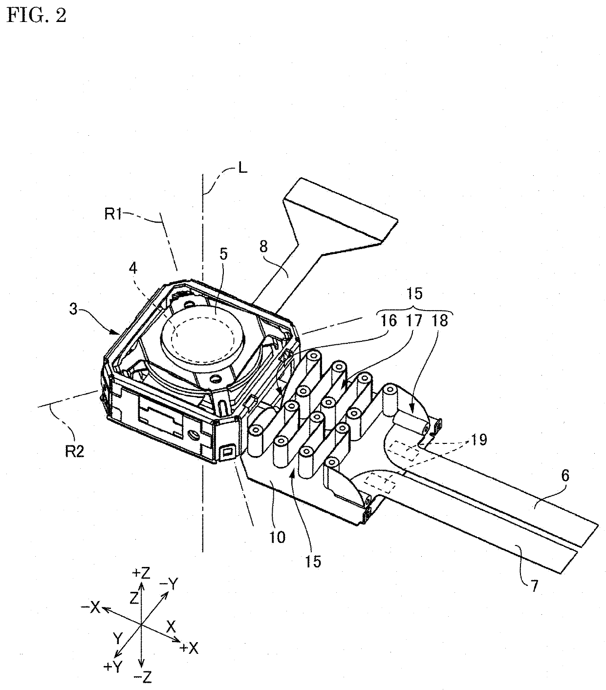
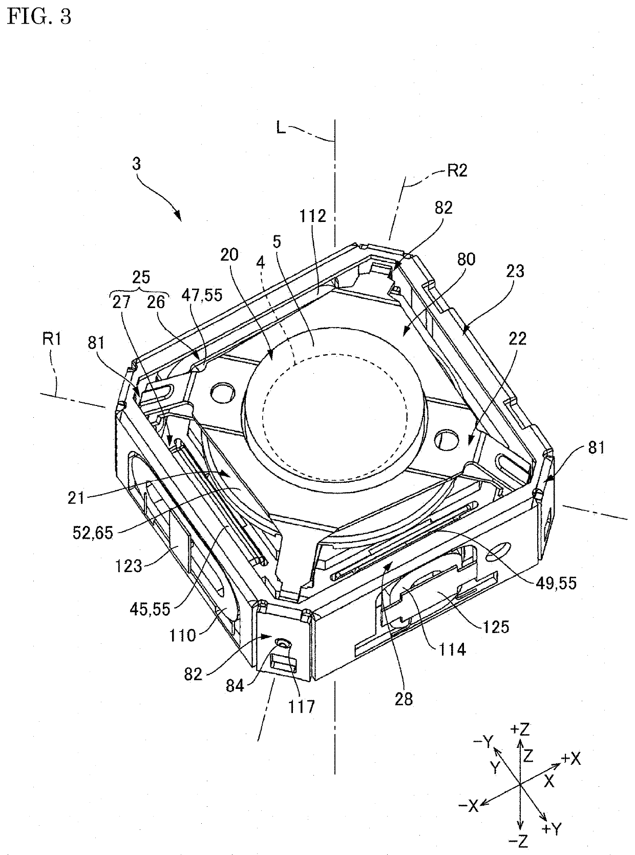
[0034]FIG. 1 is a perspective view of an optical unit 1 with a shake correction function. FIG. 2 is a perspective view of the optical unit 1 with a shake correction function from which an object-side cover has been removed. FIG. 3 is a perspective view of an optical-unit main body 3. FIG. 4 is a plan view of the optical-unit main body 3 when viewed in an optical axis direction. A first flexible printed board 6, a second flexible printed board 7, and a third flexible printed board 8 extending from the optical-unit main body 3 are omitted from the illustrations in FIG. 3 and FIG. 4. FIG. 5 is a cross-sectional view taken along the line A-A in FIG. 4. FIG. 6 is a cross-sectional view taken along the line B-B in FIG. 4. FIG. 7 is an exploded perspective view of the optical-unit main body 3.

[0035]A...


PUM


Abstract

In an optical unit with a shake correction function, a rotation support structure, which supports a movable body rotatably around an optical axis, may be supported by a gimbal structure rotatably around a first axis and a second axis intersecting with the optical axis so that, even when the movable body is rotating around the first axis or the second axis, the rotation axis of the movable body by the rotation support structure coincides with the optical axis of the movable body.

Description

CROSS REFERENCE TO RELATED APPLICATION[0001]The present invention claims priority under 35 U.S.C. § 119 to Japanese Application No. 2019-147310 filed on Aug. 9, 2019, the entire content of which is incorporated herein by reference.BACKGROUNDField of the Invention[0002]At least an embodiment of the present invention relates to an optical unit with a shake correction function to rotate an imaging module around an optical axis so as to correct the shake.Description of the Related Art[0003]In some optical units installed in mobile terminals or mobile objects, a movable body including an optical module is rotated around an optical axis, a first axis perpendicular to the optical axis, and a second axis perpendicular to the optical axis and the first axis to suppress the blur of images captured during the movement of the mobile terminal or the mobile object. Japanese Patent Application Publication No. 2015-82072 discloses this type of optical unit with a shake correction function.[0004]The...

Claims


Application Information

Patent Timeline
Patent Type & Authority Applications(United States)
IPC IPC(8): G02B27/64G03B5/06
CPCG02B27/646G03B2205/0069G03B2205/0023G03B5/06G03B5/00H04N23/55H04N23/687G03B30/00G03B17/561
Inventor TAKEI, HIROMITSU
Owner SANKYO SEIKI MFG CO LTD
Why Eureka
Try Eureka