Speaker apparatus

a technology for speakers and generating units, applied in the direction of transducer details, electrical transducers, electrical apparatus, etc., can solve the problems of speaker output decline, speaker output decrease, and speaker output decrease, so as to prevent the effect of speaker output reduction caused by leaked magnetic field and increase the magnetic flux transmission resistance in the spoke par

Active Publication Date: 2016-10-25
ALPINE ELECTRONICS INC
View PDF8 Cites 11 Cited by
  • Summary
  • Abstract
  • Description
  • Claims
  • Application Information

AI Technical Summary

Benefits of technology

[0008]A path of the leaked magnetic field from the magnetic field generating unit goes from a bottom plate of a center to a frame arm, and then returns from the frame arm to the magnetic field generating unit via a space. Alternatively, the reverse route is followed. Focusing on the speaker frame described in JP 6-276597 A, the frame arm has an even width dimension and has a small transmission resistance relative to the magnetic flux. Therefore, the frame arm has a structure in which the leaked magnetic field from the magnetic field generating unit is easily attracted. However, in the speaker apparatus described in JP 6-276597 A, the magnetic field generating unit is fixed to the bottom plate on the side of the projection of the speaker frame, and each frame arm extends to a direction apart from the magnetic field generating unit towards the outer periphery direction. Therefore, a power to attract the leaked magnetic field by the frame arm is comparatively small.
[0009]On the other hand, as a speaker apparatus having a comparatively large diameter such as a woofer and a sub-woofer for vehicle, a so-called counter-drive method apparatus, in which the magnetic field generating unit is fixed to the center on the side of the recess of the iron speaker frame (support chassis), is widely used in order to make the apparatus thin. With this method, as the frame arm of the speaker frame radially extends from the center, the frame arm gets closer to the magnetic field generating unit. Therefore, a space distance between the frame arm and the magnetic field generating unit becomes short, and the leaked magnetic flux to be attracted into the frame arm increases. Then, the effect of the leaked magnetic flux on the speaker output becomes remarkable.
[0010]A purpose of the present disclosure is to provide a speaker apparatus which solves the above problems and employs a so-called counter-drive method. Also, speaker apparatuses described in the present disclosure can prevent a speaker output by a leaked magnetic field from decreasing even when a magnetic field generating unit is fixed to a side of a recess of a support chassis formed of a magnetic metal material such as iron material.
[0016]Speaker apparatuses according to the present disclosure may employ counter-drive methods. A magnetic field generating unit having a magnet is fixed to a center on a recess side of a support chassis made of the magnetic metal, and a space distance between a spoke part of the support chassis and the magnetic field generating unit becomes shorter. With this structure, the width dimension of the spoke part is formed to be smaller toward a direction of an inner end part, and a magnetic flux transmission resistance in the spoke part becomes larger. Therefore, a leaked magnetic field is hardly induced from the magnetic field generating unit to the support chassis, and accordingly, a reduction in a speaker output caused by the leaked magnetic field can be prevented.
[0017]Also, the magnetic flux transmission resistance in the spoke part can be increased by forming a hole part in the spoke part. In this case, the strength of the spoke part can be secured by forming a rib surrounding the hole part.

Problems solved by technology

When the rigidity of the speaker frame is small, there is a problem in that an oscillation is easily transmitted from a diaphragm and a Q-value decreases.
However, when a speaker magnet is formed of the iron material, a magnetic field leaked from the magnetic field generating unit is attracted into the speaker frame.
Also, a magnetic flux density in the magnetic gap where a voice coil is positioned decreases, and accordingly, a problem occurs in that a speaker output decreases.
Therefore, a space distance between the frame arm and the magnetic field generating unit becomes short, and the leaked magnetic flux to be attracted into the frame arm increases.

Method used


Image

  • Speaker apparatus
  • Speaker apparatus
  • Speaker apparatus

Examples


Embodiment Construction

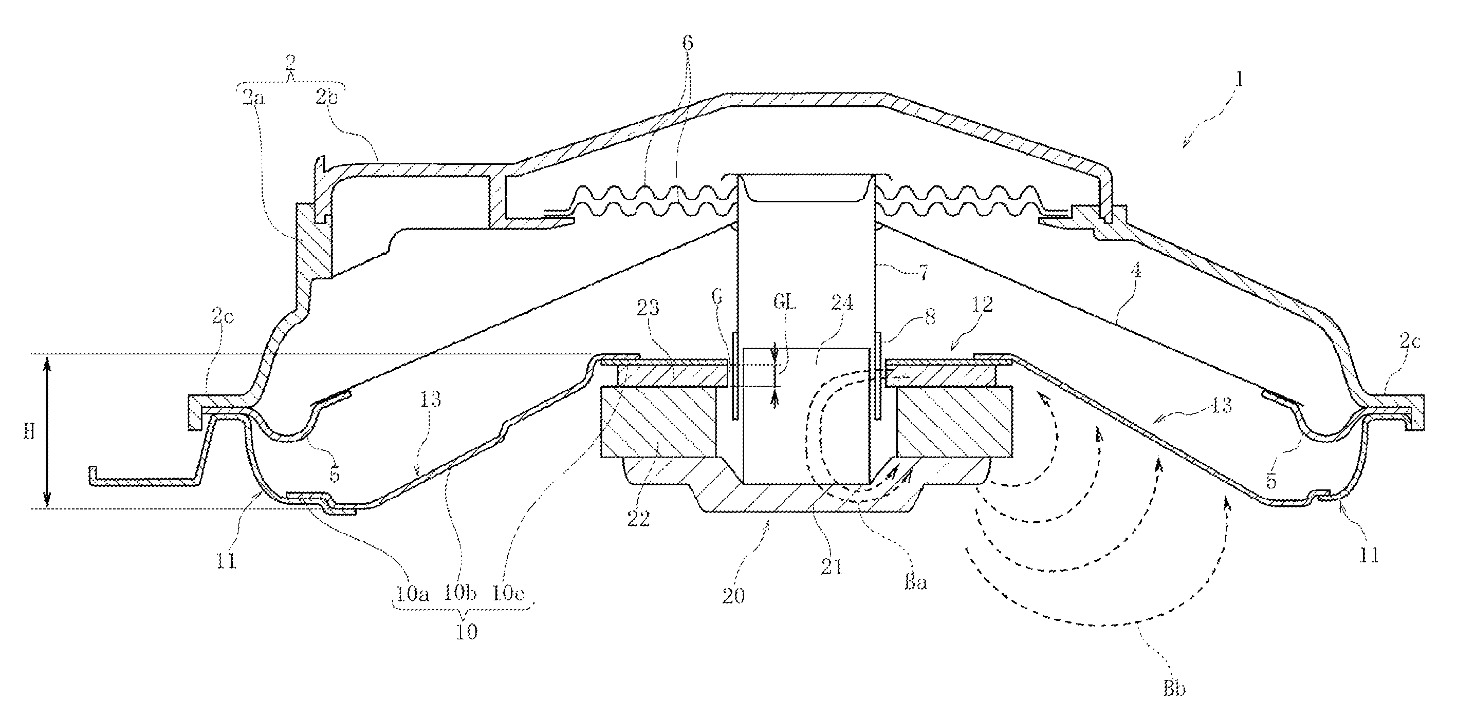
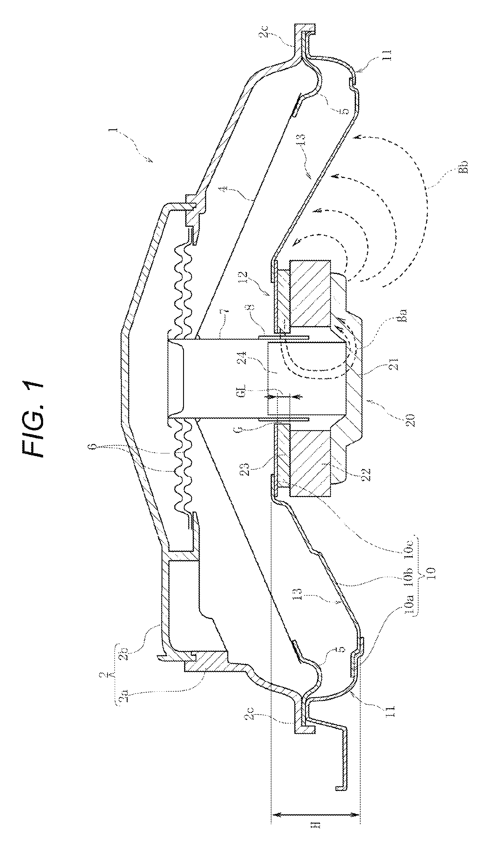
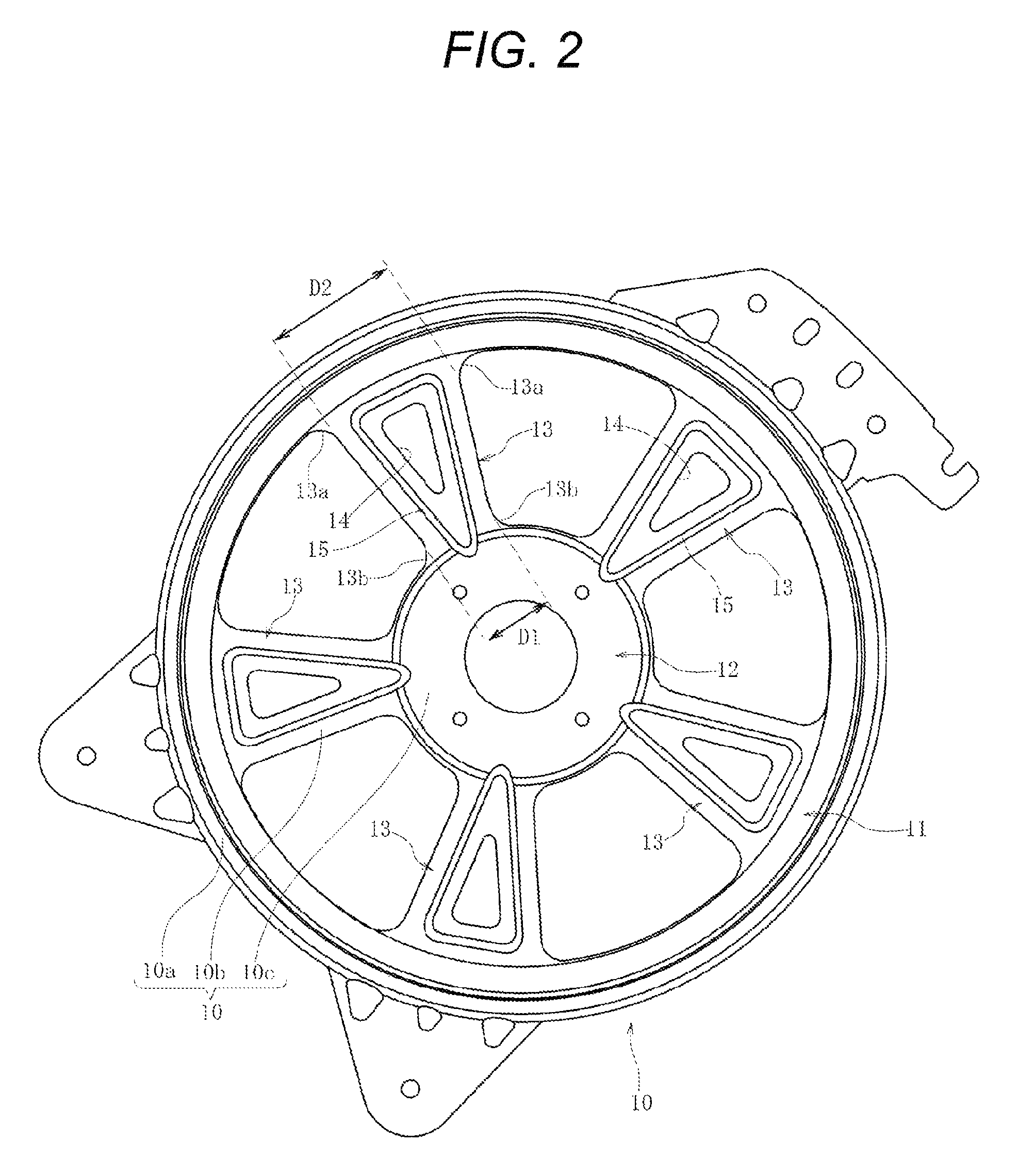
[0039]The support chassis 10 of the speaker apparatus 1 illustrated in FIGS. 1 and 2 is formed of a rolled steel plate having the thickness of 0.3 mm. It is assumed that the length of the spoke part 13 (length including R parts 13a and 13b) L illustrated in FIG. 3 be 67 mm and that a depth dimension (height dimension) H of the support chassis 10 illustrated in FIG. 1 be 34 mm. It is assumed that an opening length R in a radiation direction of the hole part 14 formed in the spoke part 13 be 33.79 mm and that the maximum width dimension W be 17.42 mm.

[0040]As indicated in Table 1 below, in Example 1, it is assumed that the width dimension D1 on the inner peripheral side of the spoke part 13 be 21.48 mm and the width dimension D2 on the outer peripheral side be 52.76 mm. The ratio D2 / D1 is 2.5. In Example 2, it is assumed that the width dimension D1 on the inner peripheral side be 14.11 mm and the width dimension D2 on the outer peripheral side be 60.3 mm. The ratio D2 / D1 is 4.3. In Ex...


PUM


Abstract

A support chassis mounted on a sounding side of a speaker apparatus is formed of an iron material. The support chassis is formed in a shape in which a central supporting part nears a main-body chassis. A magnetic field generating unit is fixed to the central supporting part on a side of a recess of the support chassis. The support chassis includes a frame part, the central supporting part, and spoke parts. In the spoke part, a width dimension D1 of an inner end part is formed narrower than a width dimension D2 of an outer end part. Therefore, a resistance in a case where a magnetic flux passes through the spoke part increases, and the leaked magnetic field is hardly induced from the magnetic field generating unit to the spoke part. Therefore, a reduction in a speaker output can be prevented.

Description

RELATED APPLICATIONS[0001]The present application claims priority to Japanese Patent Application Serial Number 2014-150617, filed Jul. 24, 2014, the entirety of which is hereby incorporated by reference.BACKGROUND OF THE INVENTION[0002]1. Field of the Invention[0003]The present disclosure relates to a speaker apparatus having a support chassis, which supports a magnetic field generating unit, made of a magnetic metal material such as iron. In particular, the present disclosure relates to a speaker apparatus having a structure in which the magnetic field generating unit is fixed to the center on a side of a recess of the support chassis.[0004]2. Description of the Related Art[0005]JP 6-276597 A discloses an invention regarding a speaker apparatus. A speaker frame is provided in the speaker apparatus that has a conical shaped portion, and a conical shaped diaphragm is arranged on a side of a recess. The side of the recess is a sounding side. A magnetic field generating unit in which a...

Claims


Application Information

Patent Timeline
Patent Type & Authority Patents(United States)
IPC IPC(8): H04R1/02H04R9/02H04R7/16H04R1/00
CPCH04R7/16H04R9/02H04R9/025H04R2209/022H04R2400/11H04R2499/13
Inventor YAMAGAMI, MASARUTADA, ARATATANABE, KEI
Owner ALPINE ELECTRONICS INC
Why Eureka
Try Eureka