
Optical sensing device

A sensing device and optical technology, which is applied to transmit the direction of sensing components, measuring devices, instruments, etc. by using optical devices, can solve the problems of inability to respond to slight changes in displacement or inclination, and poor sensing sensitivity, so as to improve sensing sensitivity and reduce Contact area, friction reduction effect

Inactive Publication Date: 2011-03-30
EDISON-OPTO
View PDF0 Cites 15 Cited by
  • Summary
  • Abstract
  • Description
  • Claims
  • Application Information

AI Technical Summary

Problems solved by technology

In other words, the optical sensing device 1 will not be able to respond to slight changes in the displacement or inclination of the object to be sensed, that is, the sensitivity of the optical sensing device 1 to changes in displacement or inclination will become poor

Method used


Image

  • Optical sensing device
  • Optical sensing device
  • Optical sensing device

Examples


Embodiment Construction

[0067] Since the optical sensing device provided by the present invention can be widely used to sense the displacement or inclination of various objects to be sensed, especially for sensing the inclination of the object to be sensed, and the related combination implementations are too numerous to enumerate, so here Without repeating them one by one, only five preferred embodiments are listed for specific description.

[0068] see Figure 5 to Figure 7 , Figure 5 It is a three-dimensional schematic diagram showing the disassembled second housing from the first housing in the optical sensing device according to the first embodiment of the present invention; Image 6 for display when Figure 5 After the second casing in is combined with the first casing, the cross-sectional view along the B-B angle of view; Figure 7 In order to show the relative positional relationship among the light emitting component, the shielding component, the shielding area and the optical sensing com...


PUM


Abstract

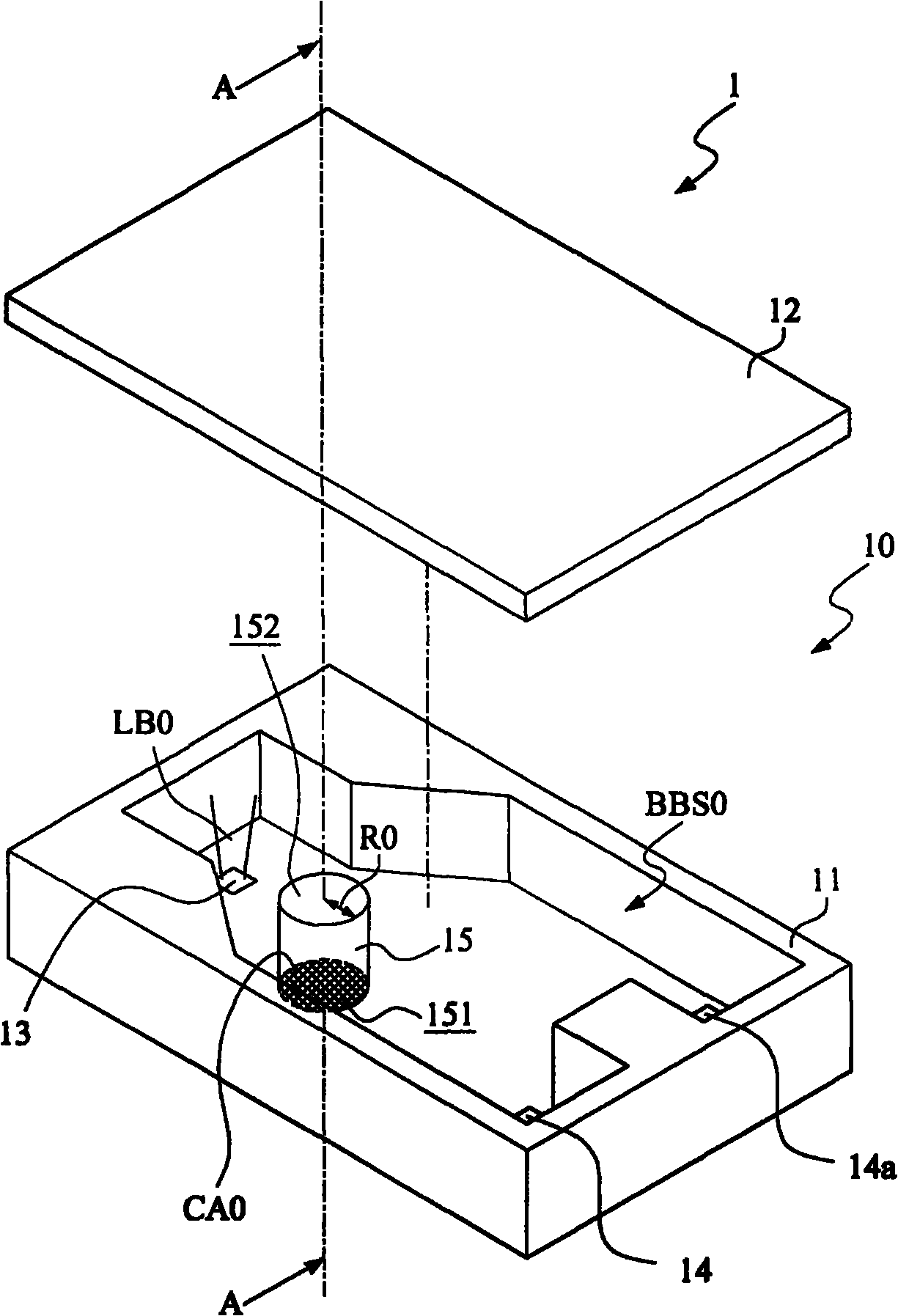
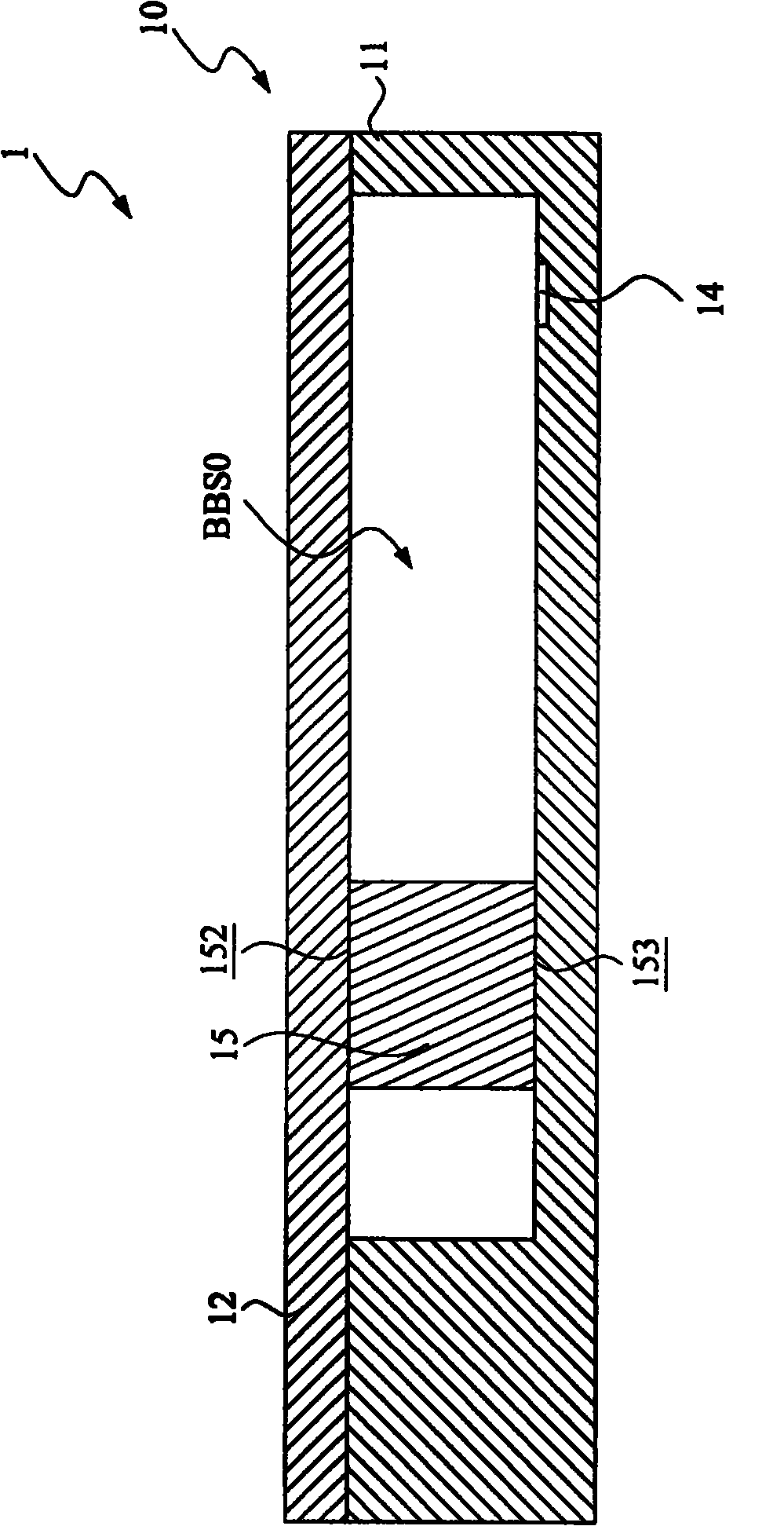
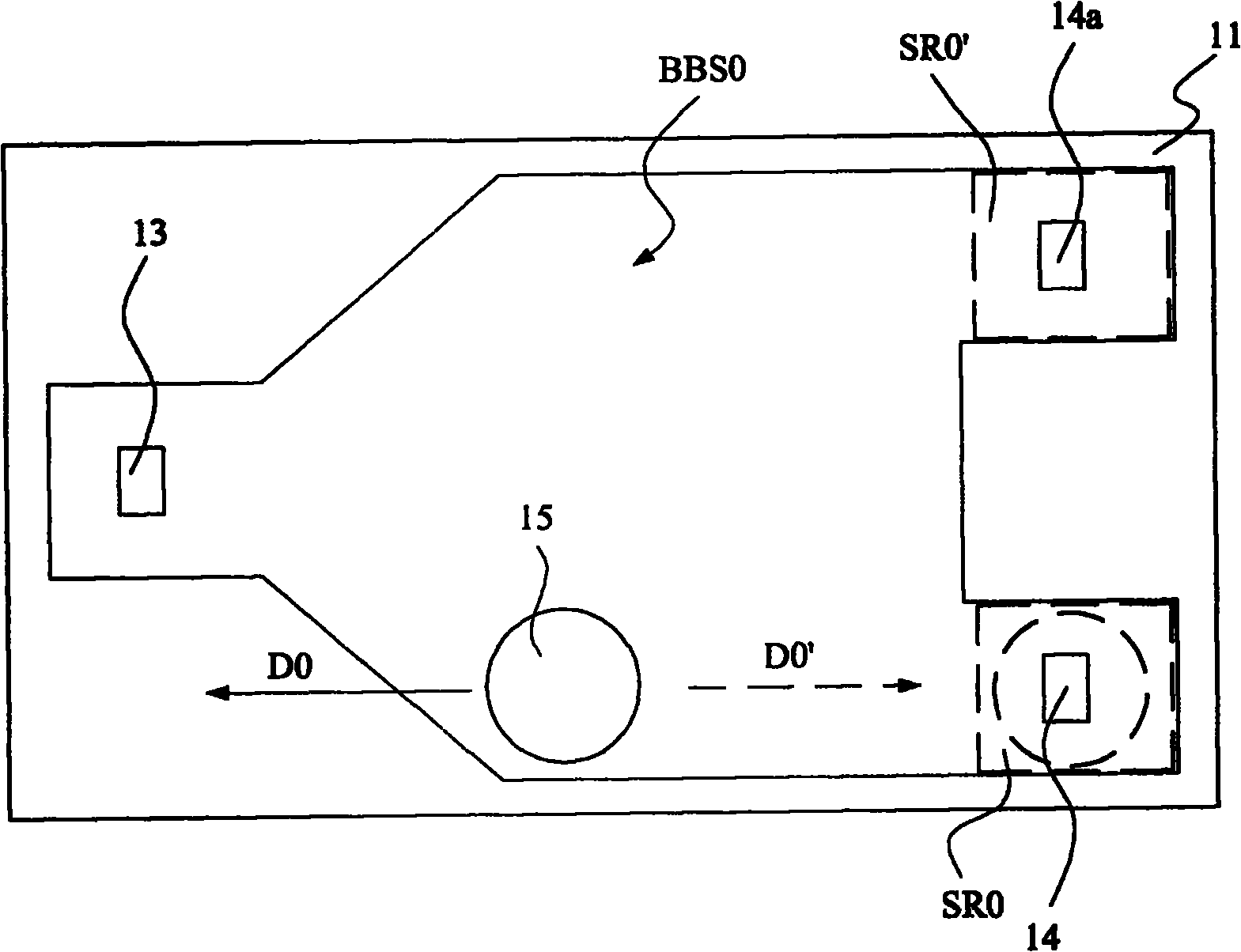
The invention discloses an optical sensing device, comprising a housing, at least one light-emitting component, at least one optical sensing component and a shading component. The inside of the housing is provided with a blackbody condition space, and the light-emitting component projects a beam towards the blackbody condition space. The optical sensing component is arranged on the housing and adjacent to the blackbody condition space. The shading component is movably arranged in the blackbody condition space and has at least one end face which is contacted with the housing and provided with at least one groove. When the shading component moves to at least one shading region of the blackbody condition space, the optical sensing component is shaded by the shading component. When the shading component departs from the shading region, the optical sensing component senses the beam to send out a sensing signal.

Description

technical field [0001] The present invention relates to an optical sensing device, in particular to an optical sensing device with high sensing sensitivity. Background technique [0002] In daily life, in order to grasp the tilt angle or displacement of an object, various sensors are usually used, and these sensors usually include a horizontal displacement sensing function, a vertical displacement sensing function or an inclination angle sensing function. In practice, these sensors usually use many sensing technologies, such as optical sensing technology, acoustic wave sensing technology or electrical sensing technology. Among them, due to the advantages of fast sensing speed, the optical sensing technology is gradually applied to the production of high-sensitivity sensing applications. [0003] On this premise, two representative existing optical sensing technologies will be listed below for specific description. see Figure 1 to Figure 3 , figure 1 It is a three-dimens...

Claims


Application Information

Patent Timeline
Patent Type & Authority Applications(China)
IPC IPC(8): G01C9/10G01C9/02G01D5/34
Inventor 冯仲平
Owner EDISON-OPTO
Learn More