Palpation diagnostic device

a diagnostic device and pressure change technology, applied in diagnostics, medical science, packaging, etc., can solve the problems of vital data, misdiagnosis and undesirable outcomes, and inability to practically measure and record examinations and treatments in these important fields, and achieve the effect of consistent diagnosis

Inactive Publication Date: 2016-01-21
NAT CHENG KUNG UNIV
View PDF0 Cites 8 Cited by
  • Summary
  • Abstract
  • Description
  • Claims
  • Application Information

AI Technical Summary

Benefits of technology

[0010]The object of the present invention is to provide a device for sensing pressure, and to provide information based on quantitative feedback for the users so that a more consistent diagnosis can be made.

Problems solved by technology

The results of examinations and treatments in these important fields cannot be practically measured or recorded.
As a result, trial and error still plays a major role, and further leads to misdiagnosis and undesirable outcomes.
These have resulted in vital data but are limited to the application of the forces through the patient to the table.
However, the current tools and associated data have resulted in significant improvements in treatment, but regrettably, these varied instrumented tools and tables can only produce tool-specific data, and cannot directly measure at the clinician's point of force application.
An applied force causes relative motion between the fibers, resulting in light attenuation.
However, this design requires very precise and rigid support.
Optical touch sensors based on total internal reflection and light scattering were also demonstrated, but possess limited sensitivity and repeatability reliant on the cleanness of the fingertip.

Method used


Image

  • Palpation diagnostic device
  • Palpation diagnostic device
  • Palpation diagnostic device

Examples


Embodiment Construction

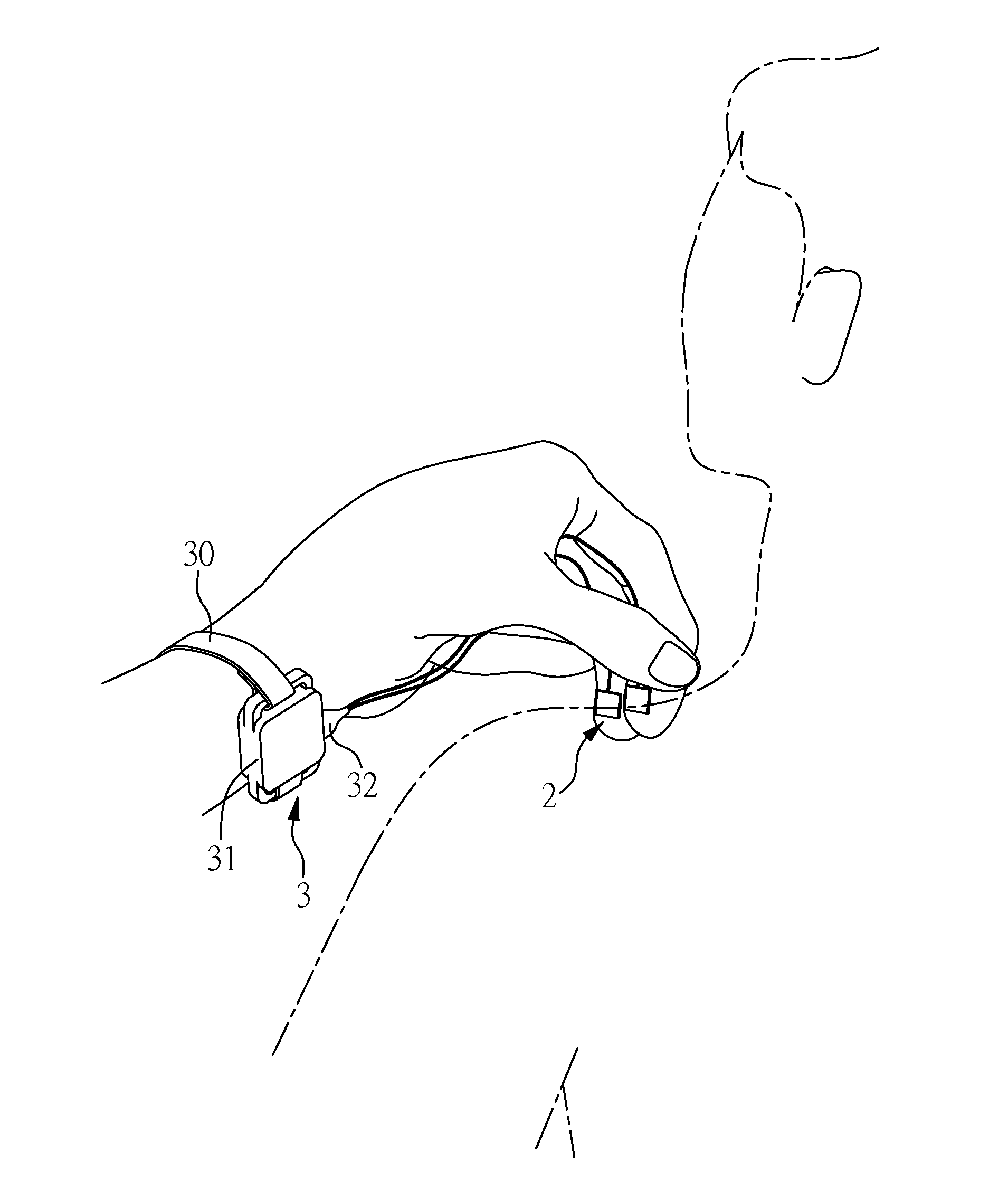
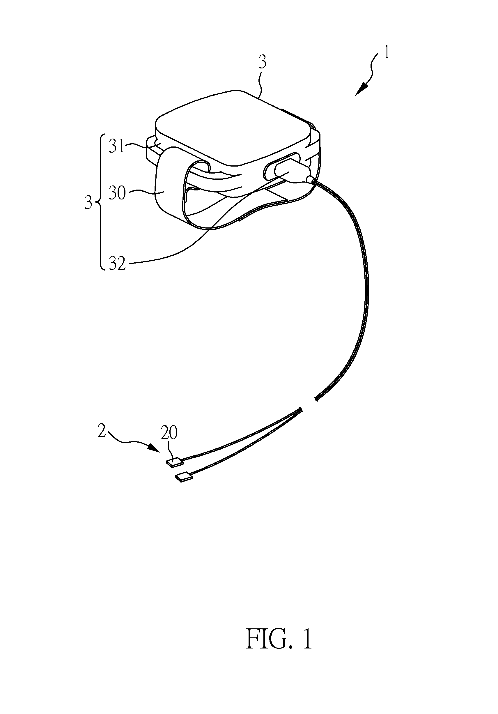
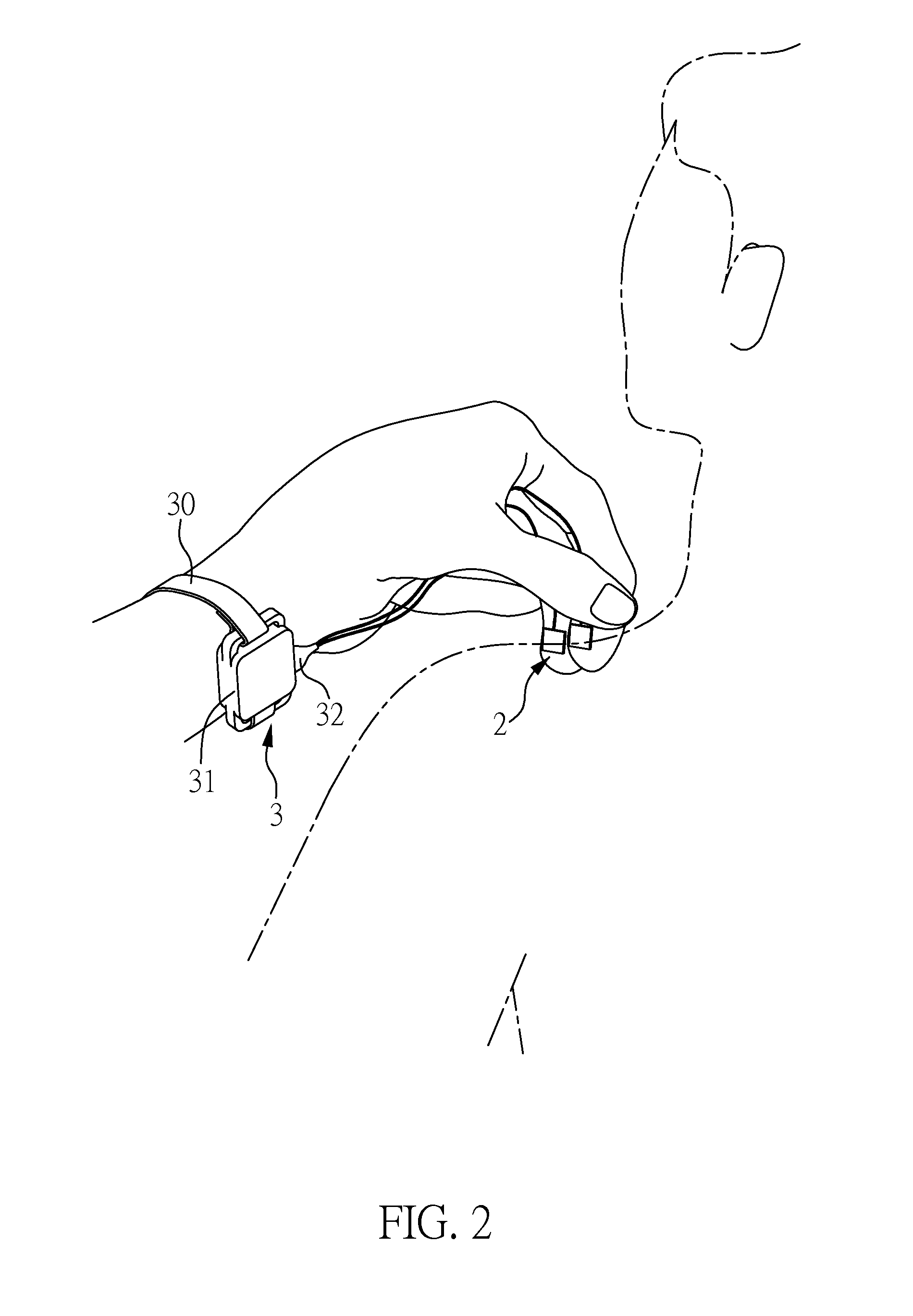
[0042]With reference to FIG. 1 and FIG. 2, a schematic diagram and a using schematic diagram of a palpation diagnostic device according to a preferred embodiment of the present invention. As shown in FIG. 1, a palpation diagnostic device 1 comprising a plurality of optical pressure sensor 2 and control device 3. Every optical pressure sensor 2 is embedded in a holder 20 which is a pad or a glove, and can be an optical fiber sensor or a micro-fabricated waveguide sensor to be disposed on a finger or a palm. In the present embodiment, the holder 20 is a pad. The control device 3 is electrically coupled to the optical pressure sensor 10, including a wrist cuff 30, a housing 31 and a connector 32.

[0043]Then, with reference to FIG. 2, the wrist cuff 30 is connected to the connector 32 so that the palpation diagnostic device 1 can be sleeved through the user's wrist by using the wrist cuff 30, and the connector 32 is electrically coupled to electronic components in the housing 31 and the ...


PUM


Abstract

The present invention relates to a palpation diagnostic device, which comprises an optical pressure sensor embedded in a holder; wherein the optical pressure sensor is an optical fiber sensor, or a micro-fabricated waveguide sensor to be disposed on a finger or a palm; and the optical pressure sensor is configured to receive an optical signal whose intensity is attenuated when a force is applied on the optical pressure sensors. Therefore, the palpation diagnostic device of the present invention can provide high sensing sensitivity by attenuating the intensity of the optical signal in the optical pressure sensors which a force is applied on, so it can provide precise and immediate information based on quantitative feedback for the users.

Description

BACKGROUND OF THE INVENTION[0001]1. Field of the Invention[0002]The present invention relates to a palpation diagnostic device, and more particularly, to a pressure change sensing device adapted for medical treatment.[0003]2. Description of Related Art[0004]Patient diagnosis and treatment frequently involves the clinician placing hands upon the patient and manually manipulating joints and muscles. Touch and pressure frequently play a significant role in diagnosing and treating disease. For example, a surgeon learns through experience what a healthy liver feels like and how it differs from a diseased or damaged organ. A chiropractor relies on previous work and memory to assess and treat a patient with a painful spine. A physical therapist sets a shoulder or stretches a muscle with a specific force that will help heal an injury without causing harm. In all of these cases, clinicians apply forces that need to be sensitive and accurate, and they currently do so without quantitative feed...

Claims


Application Information

Patent Timeline
Patent Type & Authority Applications(United States)
IPC IPC(8): A61B5/00
CPCA61B5/0053A61B5/6826A61B5/6839A61B5/0004A61B2562/223A61B2562/0266A61B2560/0412A61B2562/164A61B2562/0247A61B5/6824A61B5/6843
Inventor WANG, WEI-CHIHCHANG, CHIH-HANSU, FONG-CHINLINDERS, DAVID
Owner NAT CHENG KUNG UNIV
Why Eureka
Try Eureka