Battery test fixture with calibrations

A battery testing and fixture technology, applied in the field of mechatronics, can solve the problems of inconsistent adjustment distance between upper and lower fixtures, large error in test results, poor contact, etc., so as to reduce wages and maintenance funds, reduce the time required for testing, and prolong the service life of equipment Effect

Active Publication Date: 2011-03-30
DONGGUAN LARGE ELECTRONICS CO LTD
View PDF6 Cites 2 Cited by
  • Summary
  • Abstract
  • Description
  • Claims
  • Application Information

AI Technical Summary

Problems solved by technology

[0002] In the battery test system, different types of batteries need different installation fixtures. However, when testing batteries of different sizes, the current battery test fixtures in the industry and on the market need to use a screwdriver to adjust the distance between the upper and lower fixtures. The scale standard is for reference, so problems such as inconsistency and inappropriate adjustment distances of the upper and lower fixtures often occur during operation, resulting in poor contact and inaccurate final test data
Furthermore, the existing battery test fixtures need to use tools to adjust the upper and lower fixtures when testing batteries of different sizes, which takes a long time, and because the upper and lower fixtures cannot be at the same level, it is easy to cause inconsistent battery contact internal resistance and test results. The error is large, the fixture is easily damaged, and it is easy to cause misjudgment of qualified batteries

Method used


Image

  • Battery test fixture with calibrations
  • Battery test fixture with calibrations

Examples


Embodiment Construction

[0017] In order to further illustrate the technical means adopted by the present invention and its effects, the following describes in detail in conjunction with preferred embodiments of the present invention and accompanying drawings.

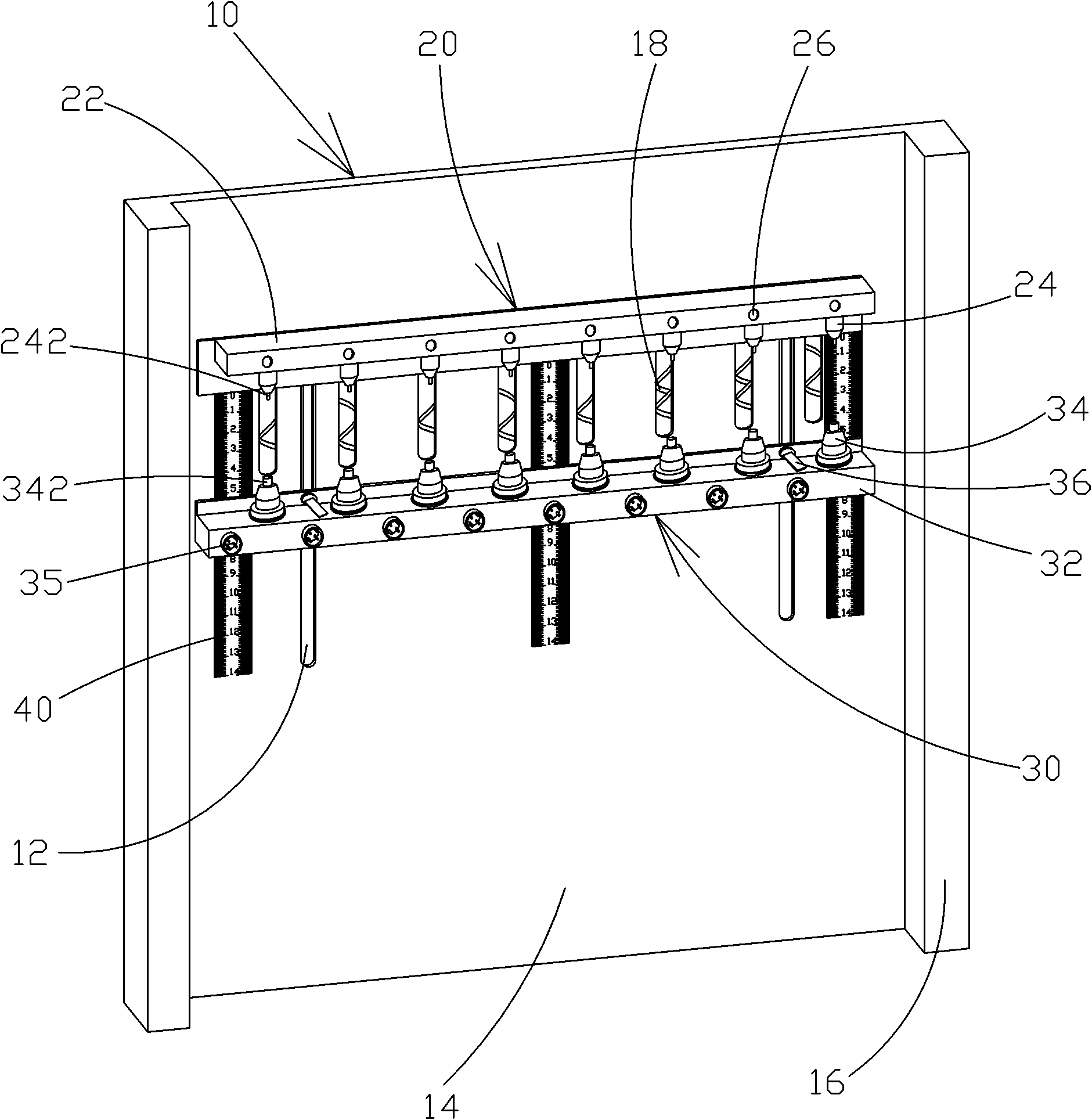
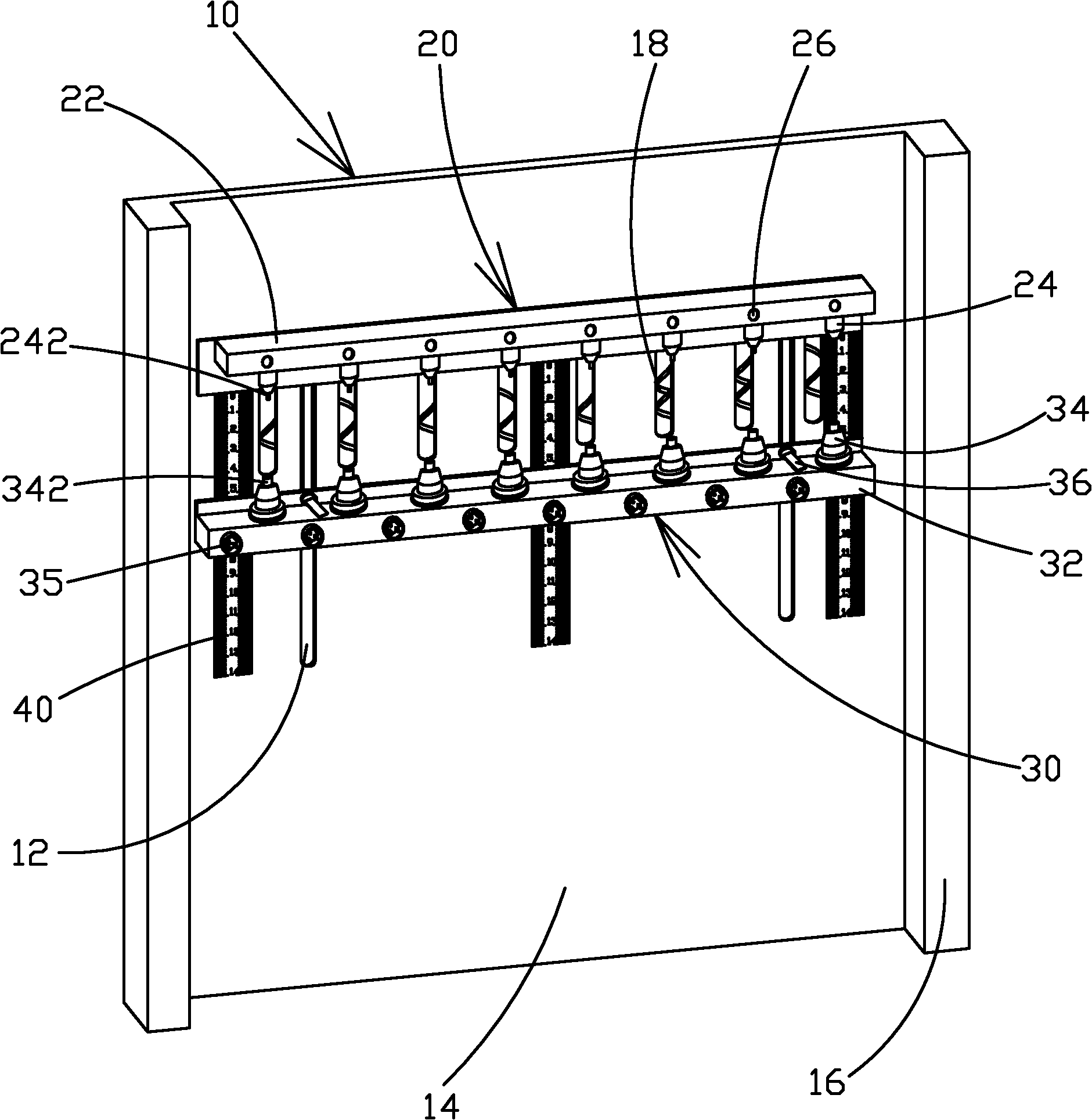
[0018] like figure 1 As shown, the present invention provides a battery test fixture with a scale, which includes: a base 10, an upper fixture 20 disposed on the base 10, and a lower fixture 30 corresponding to the upper fixture 20 disposed on the base 10 , and along the upper clamp 20 vertically downwardly arranged on several scales 40 with scales on the base 10; the two sides below the upper clamp 20 on the base 10 are respectively provided with a sliding track 12, the upper clamp 20 Including the upper splint 22 and several upper test contacts 24 arranged on the lower side of the upper splint 22, the lower fixture 30 includes the lower splint 32, several upper test contacts 24 corresponding to the upper test contacts 24 arranged on the uppe...


PUM


Abstract

The invention provides a battery test fixture with calibrations. The battery test fixture comprises a base, an upper fixture arranged on the base, a lower fixture and a plurality of rulers with calibrations, wherein the lower fixture is arranged on the base and opposite to the upper fixture; the rulers are arranged on the base vertically along the upper fixture; the both sides of the base under the upper fixture are separately provided with a sliding rail; the upper fixture contains an upper clamping plate and a plurality of upper test contacts on the lower side of the upper clamping plate; the lower fixture contains a lower clamping plate, a plurality of lower test contacts which are arranged on the upper side of the lower clamping plate and opposite to the upper test contacts, and adjusting knobs which are arranged on the both sides of the lower clamping plate and correspond to the sliding rails; the upper ends of the rulers are at the same level of the upper clamping plate, the lower ends extend vertically and are lower than the upper clamping plate; and by adjusting the adjusting knobs on the lower clamping plate, the lower fixture can move up and down along the rulers in the sliding rail. A plurality of rulers with calibrations are arranged on the both ends and middle of the test fixture of the invention and the distance between the upper and lower fixtures can be adjusted at once by adjusting the knobs, thus the work efficiency can be increased.

Description

technical field [0001] The invention relates to the field of mechanics and electronics, in particular to a battery test fixture with scales. Background technique [0002] In the battery test system, different types of batteries need different installation fixtures. However, when testing batteries of different sizes, the current battery test fixtures in the industry and on the market need to use a screwdriver to adjust the distance between the upper and lower fixtures. The scale standard is for reference, so problems such as inconsistent and inappropriate adjustment distances of the upper and lower fixtures often occur during operation, resulting in the disadvantages of poor contact and inaccurate final test data. Furthermore, the existing battery test fixtures need to use tools to adjust the upper and lower fixtures when testing batteries of different sizes, which takes a long time, and because the upper and lower fixtures cannot be at the same level, it is easy to cause inc...

Claims


Application Information

Patent Timeline
IPC IPC(8): G01R1/04
Inventor 蒋志刚
Owner DONGGUAN LARGE ELECTRONICS CO LTD
Why Eureka
Try Eureka