Control method for voltage converter and relevant voltage converter thereof

A technology of voltage converter and control method, which is applied in the direction of high-efficiency power electronic conversion, conversion equipment without intermediate conversion to AC, climate sustainability, etc., to achieve the effect of avoiding audio noise and reducing energy consumption of opening and closing

Inactive Publication Date: 2011-03-30
LEADTREND TECH
View PDF4 Cites 3 Cited by
  • Summary
  • Abstract
  • Description
  • Claims
  • Application Information

AI Technical Summary

Problems solved by technology

If the load Z1 is light-loaded or no-loaded, the average inductor current may drop to a level very close to zero

Method used


Image

  • Control method for voltage converter and relevant voltage converter thereof
  • Control method for voltage converter and relevant voltage converter thereof
  • Control method for voltage converter and relevant voltage converter thereof

Examples


Embodiment Construction

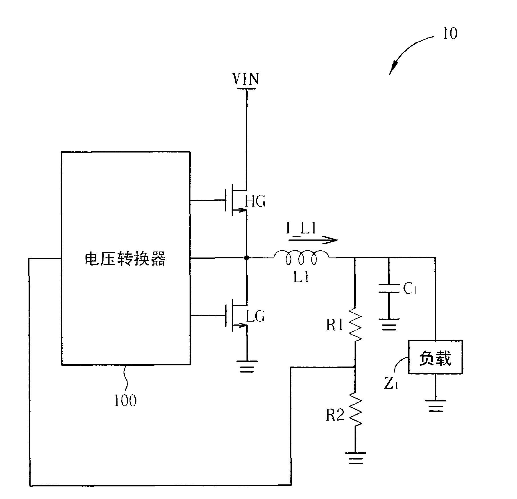
[0038] Please refer to image 3 , image 3 It is a schematic diagram of a switching power supply circuit 30 in the present invention. The power supply circuit 30 includes a power supply VIN, a voltage converter 300, an upper switch HG, a lower switch LG, an inductor L1, a capacitor C1, resistors R1, R2 and a load Z1. The biggest difference between the power supply circuit 30 and the power supply circuit 10 is that the voltage converter 100 of the prior art has been replaced by the voltage converter 300 of the present invention.

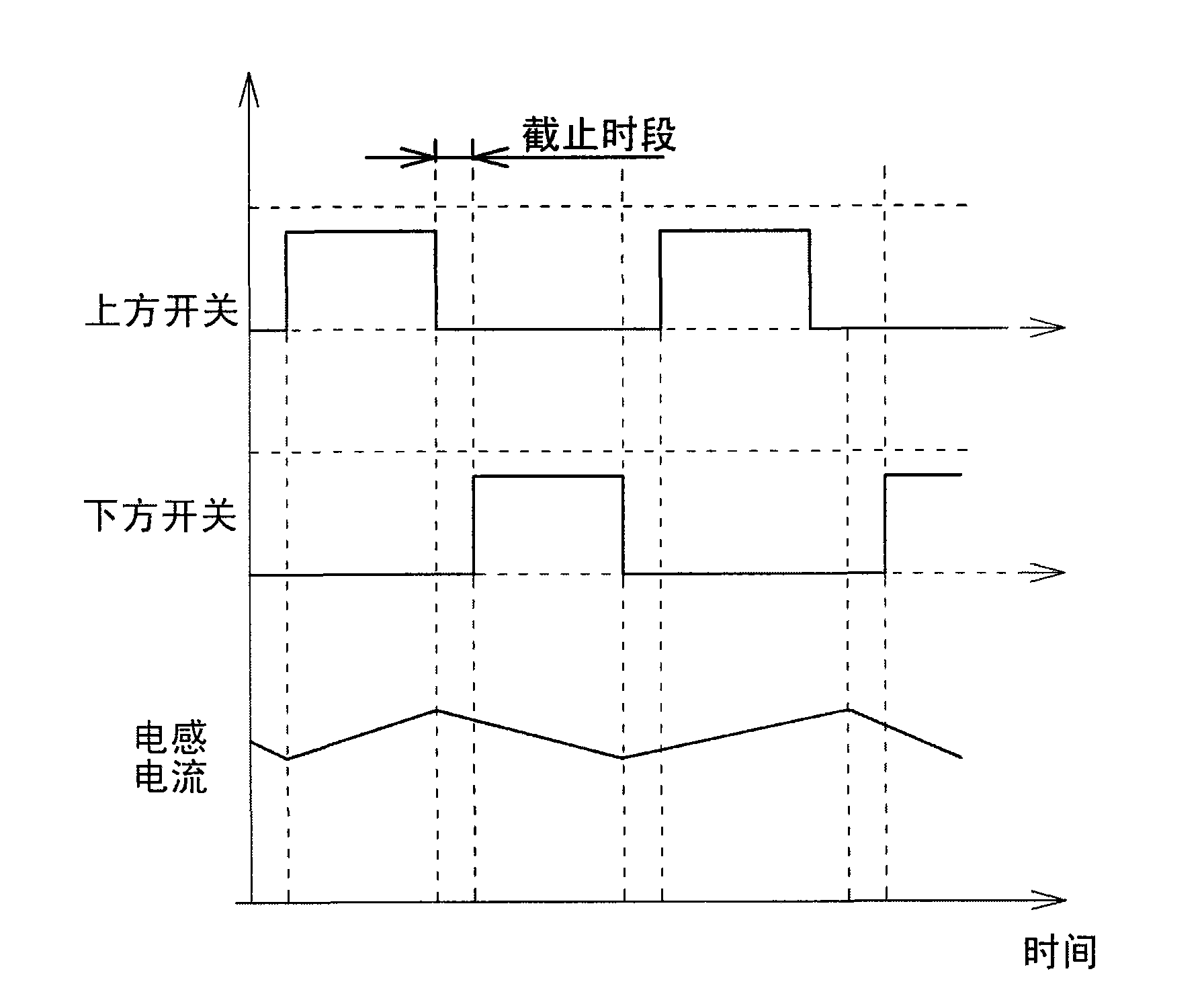
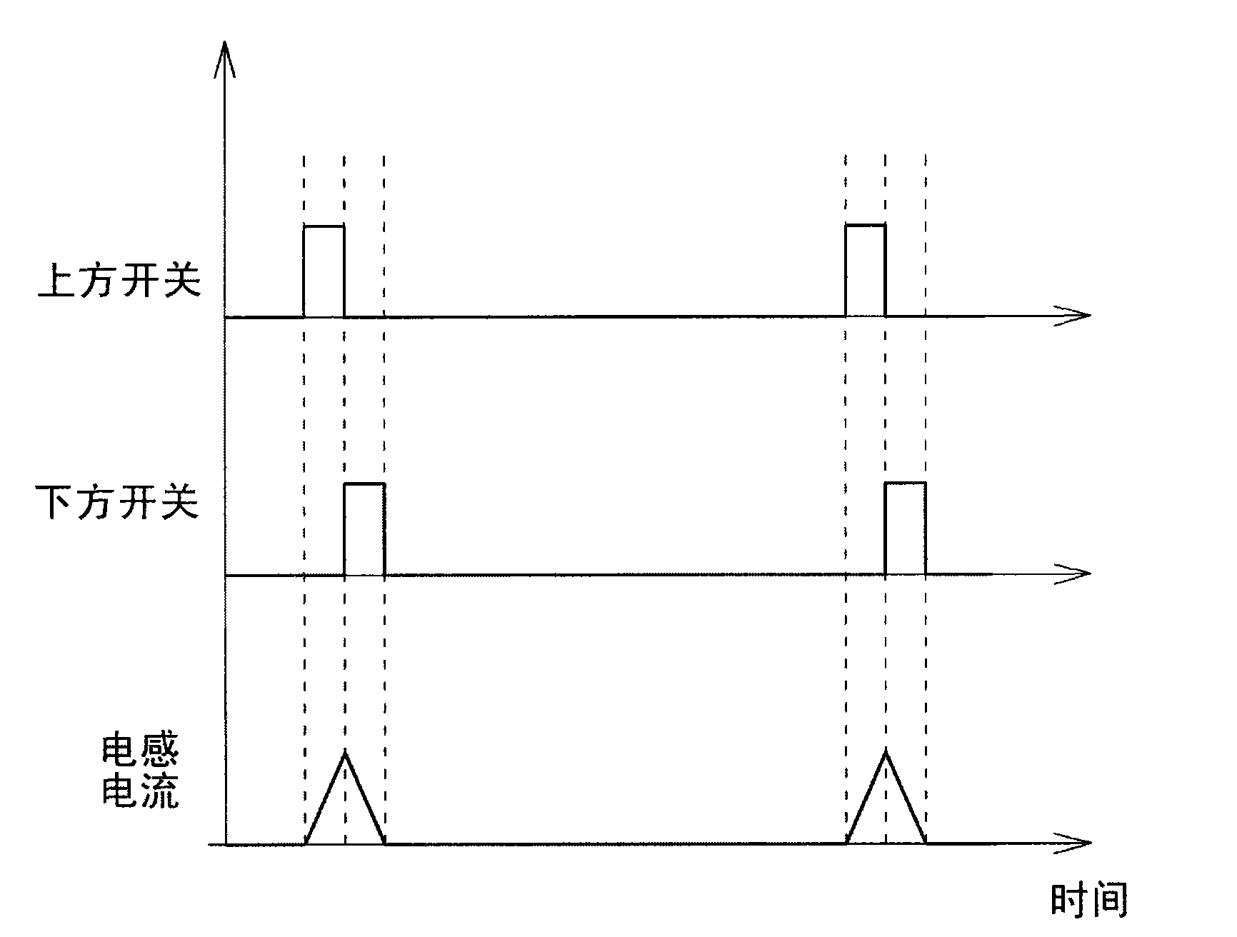
[0039] Depending on different operating conditions, the operating modes of the voltage converter 300 at least include a PWM mode and a burst mode, respectively representing a normal mode and a power-saving mode. In PWM mode, the current waveform of inductor L1 may be continuous conduction mode (CCM) or discontinuous conduction mode (DCM); it may also be because the voltage of capacitor C1 is too high that the upper switch HG and the lower switch LG ...


PUM


Abstract

The invention relates to a control method for a voltage converter and a relevant voltage converter thereof. The control method comprises the following steps of: providing a setting used for a power saving mode; entering the power saving mode to enable the voltage converter to output preset energy according to the setting; entering a normal mode to judge whether the voltage converter needs to enter the power saving mode or not and to detect the output reaction of the voltage converter; and regulating the setting according to the output reaction so that the output reaction can be approximately maintained in a preset range.

Description

technical field [0001] The present invention refers to a control method for a voltage converter and its related voltage converter, especially to a control method for a voltage converter capable of maintaining an operating frequency within a certain range in a power-saving mode operation and the related voltage converter. associated voltage converter. Background technique [0002] The existing switching power supply (switching power supply) operates in the PWM mode, and provides a stable output voltage for the load by changing the duty cycle (Duty Cycle) of a power switch in the switching cycle. When the size of the load changes, the current supplied to the load will change accordingly. An ideal switching power supply must be able to keep the output voltage stable in response to load changes. In actual usage, in order to maintain the stability of the output voltage of the switching power supply, when the load increases, the duty cycle must increase; on the contrary, if the ...

Claims


Application Information

Patent Timeline
Patent Type & Authority Applications(China)
IPC IPC(8): H02M3/10
CPCY02B70/16Y02B70/10
Inventor 李敬赞
Owner LEADTREND TECH
Why Eureka
Try Eureka