
Realization method and device of protection switching in Ethernet

A technology of protection switching and implementation method, applied in network interconnection, data exchange network, data exchange through path configuration, etc., can solve problems such as waste of network resources, improve utilization rate, realize load sharing, and avoid traffic congestion Effect

Active Publication Date: 2011-03-30
ZTE CORP
View PDF6 Cites 8 Cited by
  • Summary
  • Abstract
  • Description
  • Claims
  • Application Information

AI Technical Summary

Problems solved by technology

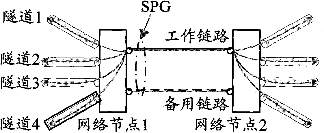
[0005] In view of this, the main purpose of the present invention is to provide a method and device for implementing protection switching in Ethernet, which can solve the problem of wasting network resources when implementing protection switching in Ethernet

Method used


Image

  • Realization method and device of protection switching in Ethernet
  • Realization method and device of protection switching in Ethernet
  • Realization method and device of protection switching in Ethernet

Examples


Embodiment Construction

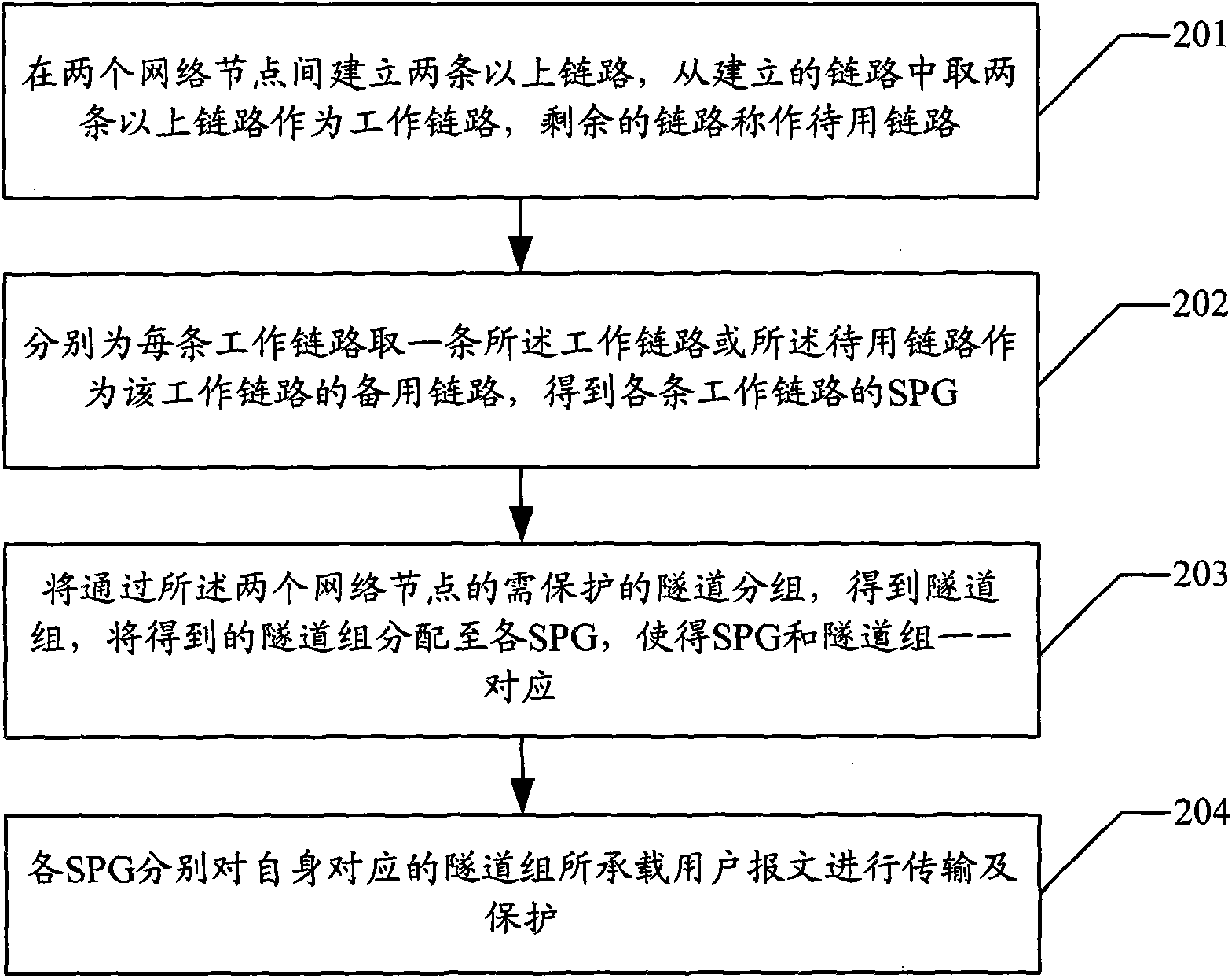
[0036] The flow of the implementation method of protection switching in Ethernet in the embodiment of the present invention is as follows: figure 2 shown, including the following steps:

[0037] Step 201: Establish two or more links between two network nodes, take more than two links from the established links as working links, and use the remaining links as standby links; The number and the number of working links are determined according to the traffic and network resources of the network nodes; when two or more links are used as working links, they can be selected arbitrarily.

[0038] Here, all established links may be used as working links, that is, there are no standby links.

[0039] Step 202: taking one of the working link or the standby link for each working link as a backup link of the working link, and obtaining the SPG of each working link;

[0040] Wherein, when all the links established are used as the working links, the said respectively taking a working link...


PUM


Abstract

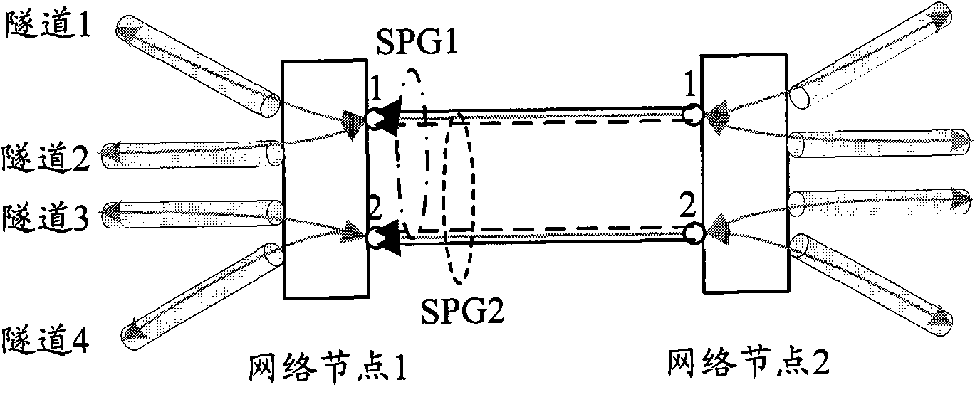
The invention discloses a realization method of protection switching in Ethernet, which comprises the following steps of: establishing more than two links between two network nodes, taking more than two links to be used as work links from the established links, and using rest links as standby links; respectively taking one work link or one standby link to be used as the standby link of the work link for each work link to obtain SPGs (Synthetic Pulse Generators) of each work link; grouping tunnels which pass through the two network nodes and need to be protected to obtain tunnel groups, and distributing the obtained tunnel groups to each SPG so that the SPGs and the tunnel groups are in one-to-one correspondence; and respectively transmitting and protecting the user message carried by the tunnel group by each corresponding SPG. Meanwhile, the invention also discloses a realization device of the protection switching in Ethernet, which comprises a setting module, a resource distributing module and a transferring module. When the method and the device of the invention are adopted, the problem of network resource waste while realizing the protection switching in Ethernet can be solved.

Description

technical field [0001] The invention relates to protection switching technology in data transmission, in particular to a method and device for realizing protection switching in Ethernet. Background technique [0002] Carrier Backbone Bridging Technology Supporting Traffic Engineering (PBB-TE) is a new type of Ethernet bearer technology. The end tunnel protects the user message to be protected; wherein, the tunnel carrying the user message to be protected is the tunnel to be protected; the TESI is composed of <backbone network destination MAC, backbone network source MAC, backbone network VLAN> ternary Group determination, that is, <B-DA, B-SA, B-VID>, used to indicate the source address, destination address and incoming virtual local area network (VLAN) of the tunnel, and encapsulate the user packet in the tunnel, that is, at the entrance of the tunnel Encapsulate the TESI of the tunnel in the header of the user packet; the protection switching scheme is specifi...

Claims


Application Information

Patent Timeline
Patent Type & Authority Applications(China)
IPC IPC(8): H04L12/56H04L12/46H04L12/24H04L12/28
CPCH04L67/1002H04L67/1001
Inventor 敖婷
Owner ZTE CORP
Learn More