Check patentability & draft patents in minutes with Patsnap Eureka AI!

Method, device and system for establishing differentiated services code point (DSCP) mapping relation between network elements

A technology of mapping relationship and establishing method, which is applied in the field of communication, can solve problems such as high maintenance cost, manpower consumption, and complicated IP transmission network, and achieve the effect of simple operation and maintenance and reduced manpower input

Active Publication Date: 2011-03-30
HUAWEI TECH CO LTD
View PDF9 Cites 3 Cited by
  • Summary
  • Abstract
  • Description
  • Claims
  • Application Information

AI Technical Summary

Problems solved by technology

The entire IP transmission network is intricate, and multiple services are simultaneously transmitted on one IP network
Among them, the dynamic routing of the IP network and the convergence of the intermediate network are varied. To obtain the current designated service transmission path, a certain amount of manpower is required, and the operation and maintenance cost is high.
[0010] 2. It is necessary to invest a large number of technical experts to check whether each node on the current transmission path has modified the DSCP value and the mapping relationship of the DSCP value
There are many network element devices on a path, and a large number of configuration DSCP mapping tables requires a lot of manpower, and the calculation is quite difficult
[0011] To sum up: each step of the existing technology requires a lot of manual participation, which increases the maintenance cost and complicates the overall process operation

Method used


Image

  • Method, device and system for establishing differentiated services code point (DSCP) mapping relation between network elements
  • Method, device and system for establishing differentiated services code point (DSCP) mapping relation between network elements
  • Method, device and system for establishing differentiated services code point (DSCP) mapping relation between network elements

Examples


Embodiment 1

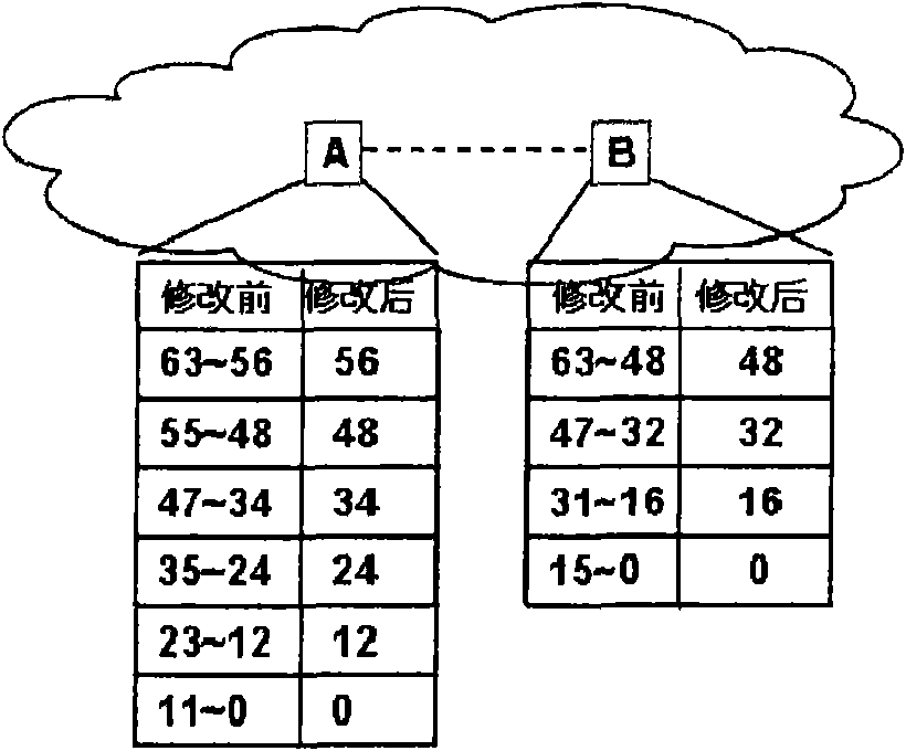
[0045] This embodiment provides a method for establishing a DSCP mapping relationship between network elements. The DSCP value in the payload is used to remain unchanged during message transmission, and the DSCP value in the message header will be changed by each network on the transmission path. The mechanism of element change is to establish the DSCP mapping relationship between network elements.

[0046] The method of this embodiment includes a detection execution phase, and optionally, a trigger phase and a detection negotiation phase may be included before the detection. In the trigger phase and the detection negotiation phase, this embodiment refers to the party that triggers and initiates the detection negotiation as the active party, and the other party that cooperates with the detection negotiation process is called the activated party; in the detection execution phase, this embodiment will actively initiate the detection The network element is called the source end, the...

Embodiment 2

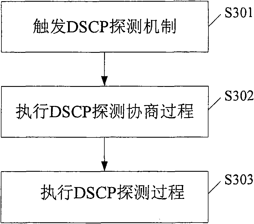
[0115] This embodiment provides a method for establishing a DSCP mapping relationship between network elements. Different from Embodiment 1, this embodiment only implements forward DSCP detection, that is, establishes the DSCP value configured by the source itself from the source to the destination. DSCP forward mapping relationship, and inform the source of the established DSCP forward mapping relationship. The method of this embodiment can also include image 3 The three steps shown.

[0116] Step 1. The activation terminal triggers the DSCP detection function.

[0117] For the trigger detection function, reference may be made to the related description of step S301 in Embodiment 1.

[0118] Step 2: The active end executes the DSCP detection negotiation process.

[0119] Figure 7 This is a flowchart of the method of the DSCP detection negotiation process in this embodiment. Such as Figure 7 Shown:

[0120] Step S701: The activation terminal actively sends an activation message to...

Embodiment 3

[0177] This embodiment provides a method for establishing a DSCP mapping relationship between network elements. The difference from Embodiments 1 and 2 is that this embodiment only implements backward DSCP detection, that is, the source is obtained through the exchange of detection messages between the source and the destination. The backward DSCP mapping relationship of the DSCP value that needs to be detected from the destination to the source. In this method, the source end establishes the backward DSCP relationship mapping table, and optionally, the source end also sends the backward DSCP relationship mapping table to the destination end. The method of this embodiment also includes image 3 Three steps.

[0178] Step 1: Trigger DSCP detection function

[0179] For the trigger detection function, reference may be made to the related description of step S301 in Embodiment 1.

[0180] Step 2: Perform the DSCP detection negotiation process. The negotiation process can refer to Fi...


PUM


Abstract

The embodiment of the invention provides a method, a device and a system for establishing a differentiated services code point (DSCP) mapping relation between network elements. The method comprises the following steps of: receiving a DSCP message, wherein the payload of the DSCP message contains a first DSCP value needing to be detected, and the message header of the DSCP message contains a second DSCP value which is acquired after the first DSCP value needing to be detected is transmitted between the network elements; and establishing the DSCP mapping relation of the first DSCP value needing to be detected between the network elements according to the first DSCP value contained in the payload of the DSCP message and the second DSCP value contained in the message header of the DSCP message. The method is easy to operate, efficient and fast. By the method, the mapping relation of the DSCP values between any two network elements in the whole transmission network can be detected, the human input is greatly reduced, the problem can be more accurately found, and the method can be applied to all the universal internet protocol (IP) networks.

Description

Technical field [0001] The present invention relates to the field of communication technology, in particular to a method, device and system for establishing a DSCP mapping relationship between network elements. Background technique [0002] In recent years, Internet Protocol (IP) technology has been widely used in various fields. IP transmission supports mixed transmission of multiple services, and different priorities can be set according to the type of service. High-priority can obtain higher-level services and guarantee the transmission quality; low-priority can obtain lower-level services, and the transmission quality can only be lowered or not guaranteed. Regarding transmission quality, it can be evaluated in terms of transmission packet loss rate, transmission delay, and transmission jitter. [0003] For wireless services, the priority service mechanism of IP technology is directly related to the experience of wireless users. 3GPP sets different priorities in accordance wit...

Claims


Application Information

Patent Timeline
Patent Type & Authority Applications(China)
IPC IPC(8): H04L29/06
Inventor 陈琰琰赖志昌杨义成王江胜
Owner HUAWEI TECH CO LTD
Features
  • R&D
  • Intellectual Property
  • Life Sciences
  • Materials
  • Tech Scout
  • Unparalleled Data Quality
  • Higher Quality Content
  • 60% Fewer Hallucinations
Learn More