
Fail-safe tooling for engine crankshaft thrust washer

An engine and thrust plate technology, applied in metal processing, manufacturing tools, metal processing equipment and other directions, can solve the problems of engine quality, engine crankshaft, cylinder block wear and other problems, and achieve the effects of simple production, low cost and simple operation

Active Publication Date: 2011-04-06
BEIQI FOTON MOTOR CO LTD
View PDF5 Cites 5 Cited by
  • Summary
  • Abstract
  • Description
  • Claims
  • Application Information

AI Technical Summary

Problems solved by technology

If the assembly direction is wrong, it will cause severe wear of the engine crankshaft and cylinder block, resulting in serious engine quality problems

Method used


Image

  • Fail-safe tooling for engine crankshaft thrust washer
  • Fail-safe tooling for engine crankshaft thrust washer
  • Fail-safe tooling for engine crankshaft thrust washer

Examples


Embodiment Construction

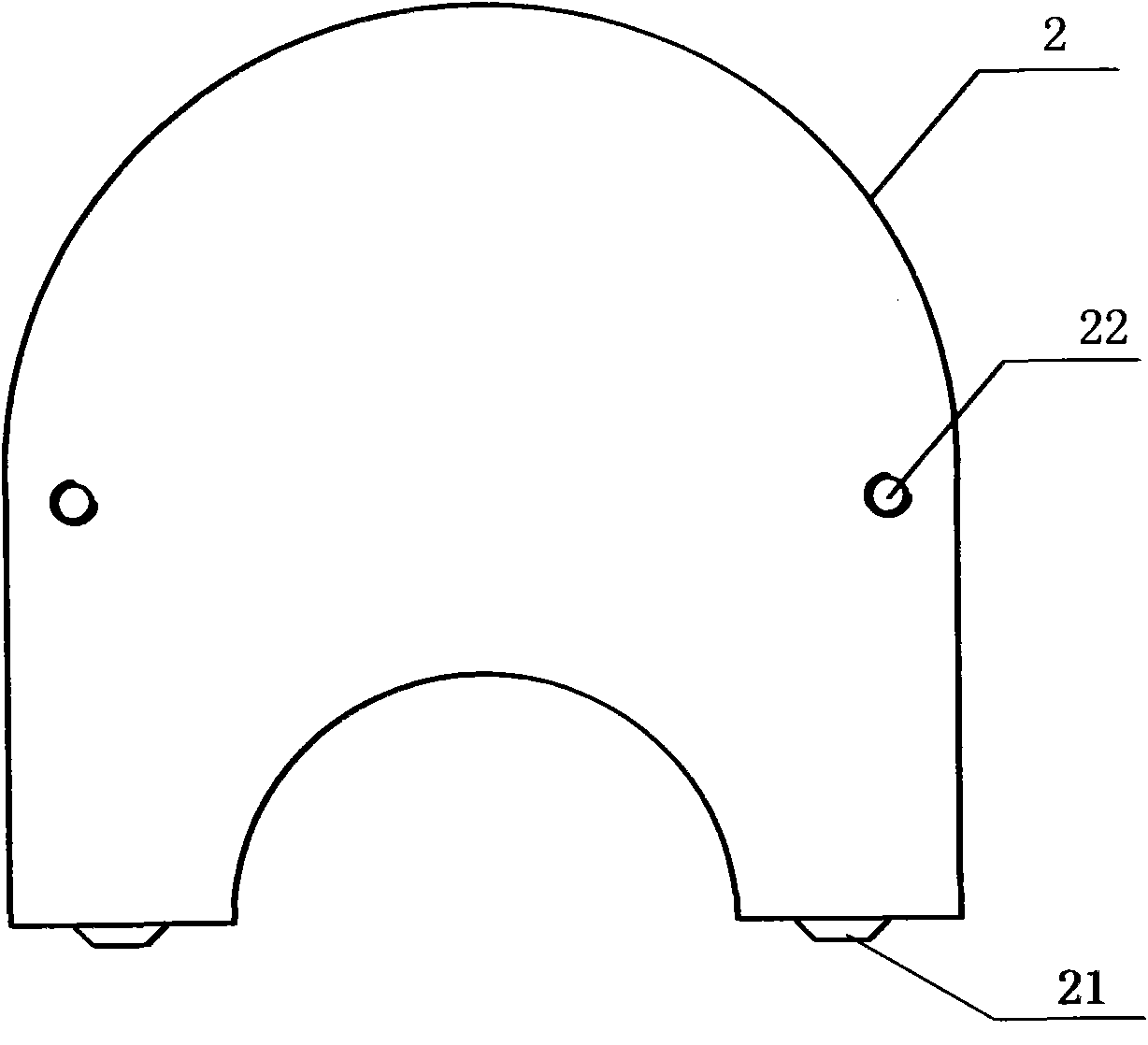
[0018] The invention includes a base body and an anti-error beam installed in the middle of the base body. See figure 2 , image 3 As shown, the cross-section of the middle part of the base body 2 is rectangular. The two ends of the bottom surface of the base body 2 are respectively provided with positioning pins 21; the middle part of the bottom surface of the base body forms an arc-shaped depression upward. The upper part of the base body is arc-shaped upwards. The substrate is provided with screw holes 22 to facilitate the installation of the error-proof beam through bolts.

[0019] See Figure 4 , Figure 5 As shown, on both sides of the central point of the side wall surface of the described anti-error beam 3, there are two protrusions 31 that match the oil groove on the engine crankshaft thrust plate symmetrically, and the distance between the two protrusions 31 is the same as The distance between the two oil grooves on the engine crankshaft thrust plate is equal....


PUM


Abstract

The invention relates to a fail-safe tooling for an engine crankshaft thrust washer. The tooling comprises a base body and a fail-safe beam, wherein the middle cross section of the base body is rectangular; the fail-safe beam is arranged at the middle part of the base body in the lengthwise direction of the rectangle; a slit of which the width is equal to the thickness of the engine crankshaft thrust washer, is arranged between the fail-safe beam and the base body; both sides of the center point of the fail-safe beam, which face one side wall surface of the base body, are symmetrically provided with two bulges which tally with oil grooves in the engine crankshaft thrust washer; and the distance between the two bulges is equal to the distance between the two oil grooves in the engine crankshaft thrust washer.

Description

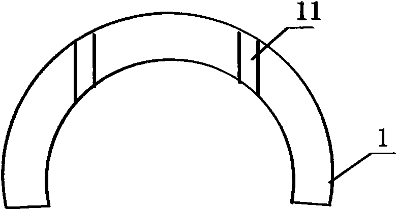
technical field [0001] The invention relates to an installation tool for automobile engine components, in particular to an installation tool for crankshaft thrust plates of an automobile engine. Background technique [0002] Typical structure of engine crankshaft thrust plate figure 1 As shown, one side of the thrust plate 1 is a plane, and two oil grooves 11 are symmetrically arranged on both sides of the center point of the other side, and the oil grooves 11 are recessed into the plane. When the engine is assembled, the thrust plate needs to be put into the thrust plate groove of the engine crankshaft. Due to the structure of the thrust plate, it is inevitable that the crankshaft thrust plate will be assembled in the wrong direction during the assembly process. Crankshaft thrust plate is a key part of the engine, and whether its assembly direction is correct directly affects the quality of the engine. If the assembly direction is wrong, it will cause severe wear of the ...

Claims


Application Information

Patent Timeline
Patent Type & Authority Applications(China)
IPC IPC(8): B23P19/00
Inventor 龚世华荆小梅
Owner BEIQI FOTON MOTOR CO LTD
Learn More