Camera module structure

A technology of camera module and boss structure, which is applied in the optical field, can solve the problems of easy loosening and vibration falling off in the fixing method of the camera, achieve the effect of simple and fast assembly operation, avoid back and forth swing deformation, and ensure the quality of the camera and the service life

Pending Publication Date: 2022-01-21
ZHEJIANG SUNNY SMARTLEAD TECH CO LTD
View PDF0 Cites 1 Cited by
  • Summary
  • Abstract
  • Description
  • Claims
  • Application Information

AI Technical Summary

Problems solved by technology

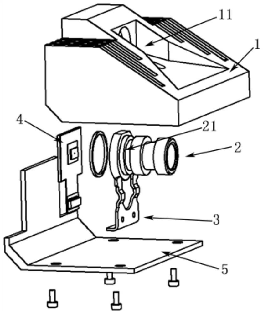
[0005] The purpose of the present invention is to provide a camera module structure, which solves the problems of easy loosening and vibration falling off in the existing camera fixing method

Method used


Image

  • Camera module structure
  • Camera module structure
  • Camera module structure

Examples


Embodiment Construction

[0037] In order to more clearly describe the embodiments of the present invention or the technical solutions in the prior art, the following will briefly introduce the drawings that are used in the embodiments. Apparently, the drawings in the following description are only some embodiments of the present invention, and those skilled in the art can also obtain other drawings according to these drawings without creative efforts.

[0038] When describing the embodiments of the present invention, the terms "vertical", "transverse", "upper", "lower", "front", "rear", "left", "right", "vertical", " The orientation or positional relationship expressed by "horizontal", "top", "bottom", "inner" and "outer" is based on the orientation or positional relationship shown in the relevant drawings, which are only for the convenience of describing the present invention and simplifying the description, and It is not to indicate or imply that the device or element referred to must have a particu...


PUM


Abstract

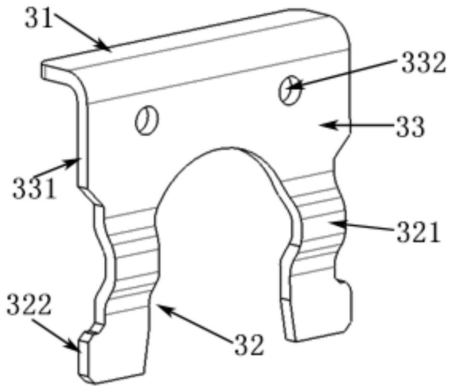
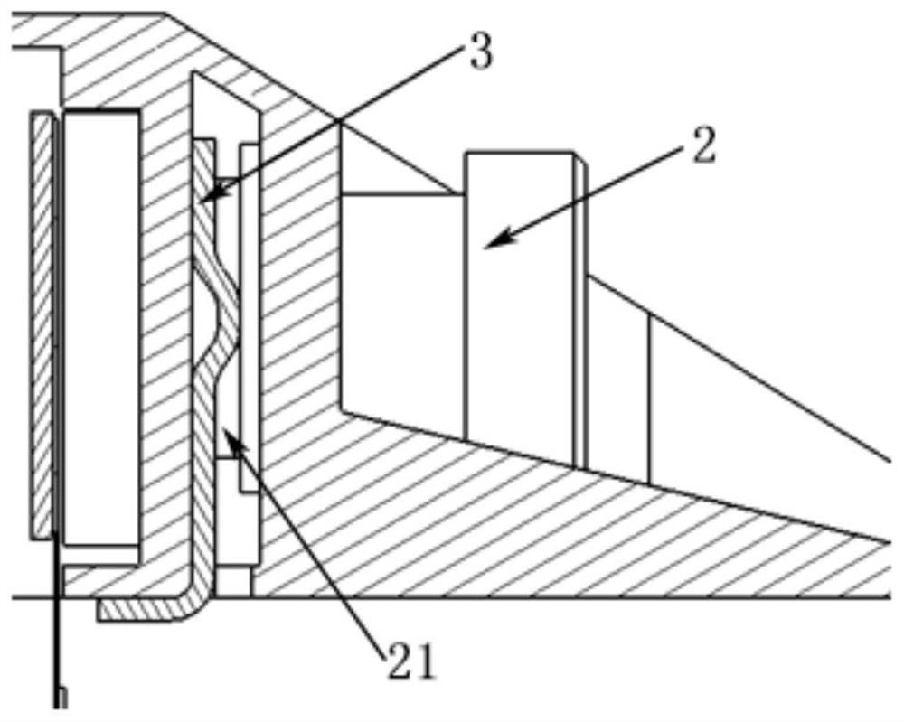
The invention relates to a camera module structure which comprises an upper shell (1) and a lens (2), the upper shell (1) is provided with a containing part (11), the lens (2) is installed in the containing part (11), the camera module structure is characterized by further comprising a clamping spring (3), the clamping spring (3) comprises a pressing part (31) and a clamping part (32), a guide groove (12) is formed in the upper shell (1), a clamping groove (21) is formed in the peripheral wall of the lens (2). And the clamping part (32) is clamped in the clamping groove (21) of the lens along the guide groove (12). The camera module structure is convenient to assemble, does not have the problems of vibration, falling off, breakage and the like compared with screw connection, glue connection and the like, and is good in imaging quality and long in service life.

Description

technical field [0001] The invention belongs to the field of optical technology, in particular to a vehicle-mounted camera module structure. Background technique [0002] Today, the automotive industry is moving towards autonomous driving, and automotive designers and developers are paying more and more attention to the active safety of automotive systems. To achieve active safety and autonomous driving, advanced driver assistance systems are the foundation and the key. [0003] The application of the camera in the auxiliary system plays a pivotal role. Through front view, rear view, side view, 360 surround view and other camera modules, functions such as adaptive cruise control, blind spot detection, collision avoidance, and parking assistance can be realized. To realize these functions, the positional relationship between the camera module and the car is very important, and the quality of the camera module fixing directly determines the effect and success of realizing the...

Claims


Application Information

Patent Timeline
Patent Type & Authority Applications(China)
IPC IPC(8): H04N5/225G03B17/55
CPCG03B17/55H04N23/51H04N23/50H04N23/55H04N23/52G03B30/00G02B7/026G02B7/02G03B17/02G03B17/563
Inventor 张扣文丁志张宝忠
Owner ZHEJIANG SUNNY SMARTLEAD TECH CO LTD
Why Eureka
Try Eureka