Cross flow pump capable of adjusting water discharge direction

A water outlet direction, cross-flow pump technology, applied in cross-flow pumps, circulation pumps, components of pumping devices for elastic fluids, etc., can solve the problems of connector falling off, high mold opening and manufacturing costs, and inconvenient installation, etc., to achieve Prevent the installation accessories from being installed incorrectly, solve the problem of axial movement and falling off, and facilitate assembly and disassembly

Pending Publication Date: 2018-12-18
中山市创星电器有限公司
View PDF8 Cites 1 Cited by
  • Summary
  • Abstract
  • Description
  • Claims
  • Application Information

AI Technical Summary

Problems solved by technology

[0003] Chinese utility model patent, the patent number is 201520073507.X, which discloses a cross-flow flow-generating pump, which is fixed on the inner wall of the fish tank through the bracket and its extension arm. The disadvantage is that the fixed bracket and its extension arm are relatively bulky Large, inconvenient to install, high mold manufacturing cost
[0004] In addition, in the existing cross-flow pump, the connector structure between the motor and the impeller cannot effectively prevent axial movement, and the axial movement of the impeller will easily cause the connector to fall off
Finally, the existing cross-flow pumps cannot swing left and right, that is, the direction of water flow cannot be adjusted left and right, which limits its application range

Method used


Image

  • Cross flow pump capable of adjusting water discharge direction
  • Cross flow pump capable of adjusting water discharge direction
  • Cross flow pump capable of adjusting water discharge direction

Examples


Embodiment Construction

[0031] The technical features of the present invention will be further described in detail below in conjunction with the drawings so that those skilled in the art can understand. It should be pointed out that the left, right, up and down in the following are relative to the directions in which the components are arranged in the drawings.

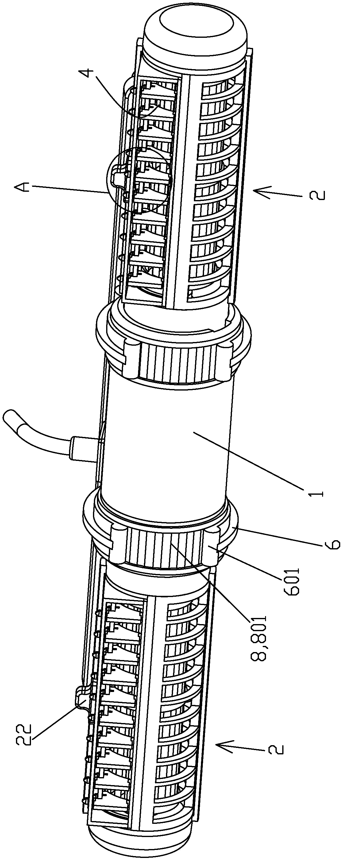
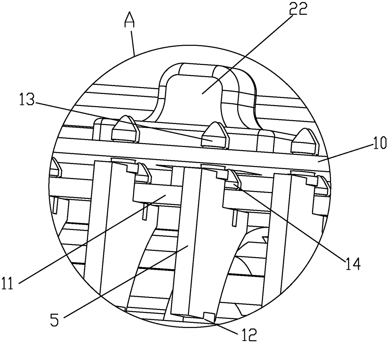
[0032] A cross-flow pump with adjustable outlet direction, such as Figure 1 to Figure 6 As shown, a motor assembly 1 is included, and two pump heads 2 are symmetrically connected on both sides of the motor assembly 1. The pump head 2 includes a pump casing 201, and a water inlet 3 and a water outlet 4 are provided on the pump casing 201. 1. The impeller 202 driven to rotate by the motor assembly 1, a plurality of water outlet blades 5 arranged side by side at the water outlet 4 and a sliding key 22 that drives the plurality of water outlet blades 5 to swing simultaneously through a linkage mechanism. Pushing the sliding key 22 left and righ...


PUM


Abstract

The invention discloses a cross flow pump capable of adjusting the water discharge direction. The cross flow pump comprises a motor assembly, pump heads are arranged on the both sides of the motor assembly, and a water inlet, a water outlet and an impeller driven by the motor assembly are arranged on each pump head. According to the technical scheme, the cross flow pump is characterized in that aplurality of water discharging blades which can swing left and right are arranged side by side at each water outlet, water discharging blades are driven by connecting rod mechanisms to swing at the same time, a manual-driven sliding button is arranged on each pump head, and the connecting rod mechanisms are driven by the sliding buttons. According to the cross flow pump, the sliding buttons are pushed left and right, and then the water discharging blades can be driven to swing left and right to realize the change of the flow direction of water at the water outlets. The motors and the impellersare connected through elastic claw mechanisms, the problem of axial swaying and falling during transmission of the motors and the impellers can be effectively solved, and assembling is simple.

Description

【Technical field】 [0001] The invention relates to a cross-flow pump capable of adjusting the water outlet direction. 【Background technique】 [0002] Cross-flow pump is the abbreviation of cross-flow flow pump, which is evolved from the working principle of cross-flow fan. The cross-flow flow-generating pump generally works in a liquid environment, and the liquid discharged is uniform and has no turbulent flow during operation, and has a good flow-generating effect. [0003] Chinese utility model patent, the patent number is 201520073507.X, which discloses a cross-flow flow-generating pump. The pump is fixed on the inner wall of the fish tank through the bracket and its extension arm. The disadvantage is that the fixed bracket and its extension arm are relatively bulky Large size, inconvenient installation, high cost of mold opening and manufacturing. [0004] In addition, in the existing cross-flow pump, the connector structure between the motor and the impeller cannot eff...

Claims


Application Information

Patent Timeline
Patent Type & Authority Applications(China)
IPC IPC(8): F04D5/00F04D29/46F04D29/18F04D29/60F04D29/00
CPCF04D5/00F04D29/007F04D29/185F04D29/466F04D29/605
Inventor 邓耀钊陈广煊张正应
Owner 中山市创星电器有限公司
Why Eureka
Try Eureka