Loudspeaker box structure

A speaker and cavity technology, applied in the field of speaker equipment, can solve problems such as the lower limit of low frequency, achieve the requirements of reducing the diameter and volume of the box, improve sound quality, and ensure the effect of radiation efficiency

Inactive Publication Date: 2013-06-05
东莞市信方科技有限公司
View PDF6 Cites 0 Cited by
  • Summary
  • Abstract
  • Description
  • Claims
  • Application Information

AI Technical Summary

Problems solved by technology

[0002] At present, the most popular speaker cavity structure is a single-cavity phase-conducting box, and its structure diagram is attached figure 1 As shown, the loudspeaker and the pipeline are placed in the same cavity, and the cavity and the pipeline form a Helmholtz resonant cavity. The resonance of the resonant cavity is tuned at a certain frequency point, and resonance occurs during operation, which is similar to the function of a band-pass filter. The back radiated sound energy is output through the pipeline in reverse phase, and is superimposed with the positive phase radiated sound energy of the speaker in the same phase, which can effectively use the back radiated sound energy of the speaker and improve the radiation efficiency of the speaker. At the same time, the lower limit of the low frequency reproduction of the open box can be It is lower than the resonant frequency of the speaker itself, but theoretically, when debugging the phase guide box with the best effect, the maximum limit of the lower limit of low frequency reproduction can only be reduced to 0.707 times, and the lower limit of low frequency is limited. there are certain requirements

Method used


Image

  • Loudspeaker box structure
  • Loudspeaker box structure
  • Loudspeaker box structure

Examples


Embodiment 1

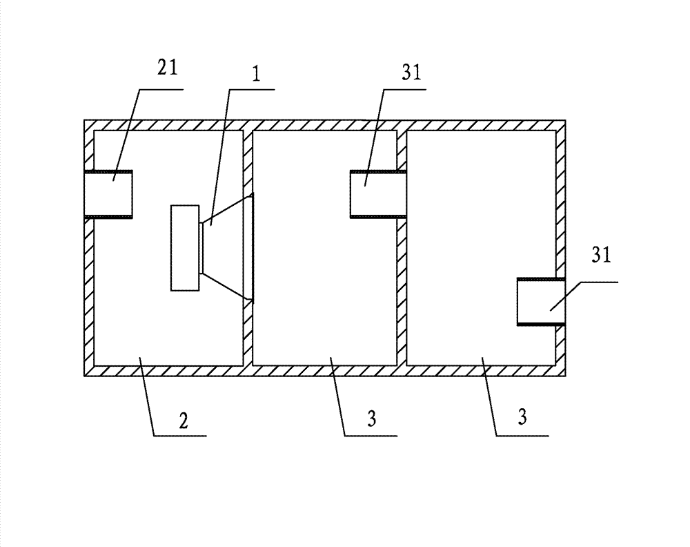
[0023] Such as figure 2 As shown, a speaker structure includes a speaker 1 and a speaker cavity. The speaker 1 is arranged in the speaker cavity. The speaker cavity includes a reverse-phase cavity unit and a normal-phase cavity unit. The reverse-phase cavity unit and the normal-phase cavity unit The speaker 1 is arranged between the anti-phase cavity unit and the normal-phase cavity unit, the anti-phase cavity unit includes at least one anti-phase resonant cavity 2 , and the normal-phase cavity unit includes at least one normal-phase resonant cavity 3 . The normal-phase resonant cavity 3 and the anti-phase resonant cavity 2 are Helmholtz resonant cavities. The normal-phase radiation sound energy of the speaker 1 is resonantly tuned through the normal-phase cavity unit, and output from the normal-phase cavity unit. The lower limit of the frequency of the radiated sound wave is lower than The lower limit of the normal-phase radiated sound wave of the speaker 1; at the same time...

Embodiment 2

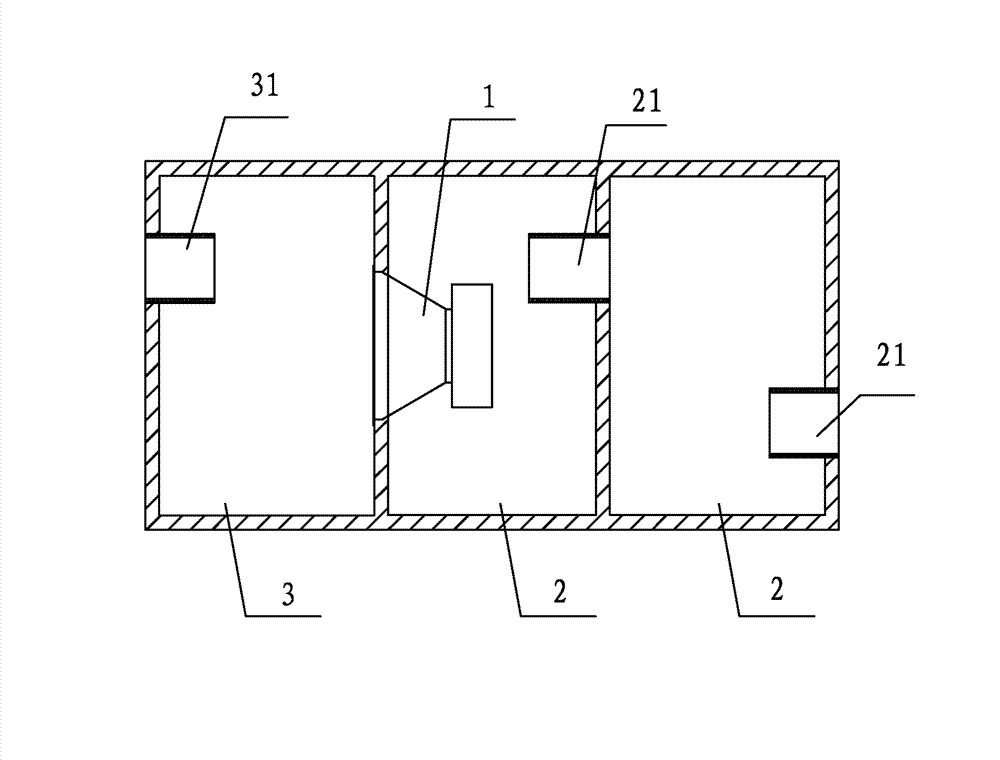
[0026] Such as image 3 As shown, the number of the normal-phase resonant cavity 3 of the present embodiment is 1, the number of the anti-phase resonant cavity 2 is 2, the first anti-phase resonant cavity 2 is connected with the normal-phase resonant cavity 3, and the second anti-phase resonant cavity 2 is connected to the first anti-phase resonant cavity 2, an anti-phase channel 21 is provided between the second anti-phase resonant cavity 2 and the first anti-phase resonant cavity 2, and the second anti-phase resonant cavity 2 is provided with an external The connected anti-phase channel 21, the normal-phase resonant cavity 3 is provided with a normal-phase channel 31 connected to the outside, and the normal-phase sound wave generated by the loudspeaker 1 is resonantly tuned by the normal-phase resonant cavity 3 of the positive-phase cavity unit to generate an anti-phase sound wave , the anti-phase sound wave passes through the normal-phase channel 31 of the normal-phase reso...

Embodiment 3

[0028] In the present embodiment 4, the number of anti-phase resonant cavities 2 is 1, and the number of normal-phase resonant cavities 3 is 4. The four normal-phase resonant cavities 3 are connected sequentially, and a positive-phase Channel 31, the normal-phase resonant cavity 3 is provided with a normal-phase channel 31 connected to the outside, and the anti-phase resonant cavity 2 is provided with an anti-phase channel 21 connected to the outside, that is to say, the first normal-phase resonant cavity 3 and the anti-phase resonant The cavity 2 is connected, the loudspeaker 1 is arranged between the first normal-phase resonant cavity 3 and the anti-phase resonant cavity 2, the anti-phase resonant cavity 2 is provided with an anti-phase channel 21 connected with the outside world, the first normal-phase resonant cavity 3 and the The second resonant cavity is connected, a positive phase channel 31 is arranged between the first positive phase resonant cavity 3 and the second re...


PUM


Abstract

The invention relates to a loudspeaker box structure which comprises a loudspeaker and a loudspeaker box cavity, wherein the loudspeaker is arranged in the loudspeaker box cavity; the loudspeaker box cavity comprises a reversed cavity unit and a positive cavity unit; the reversed cavity unit is connected with the positive cavity unit; the loudspeaker is arranged between the reversed cavity unit and the positive cavity unit; the reversed cavity unit comprises at least one reversed resonant cavity; and the positive cavity unit comprises at least one positive resonant cavity. A positive radiating sound wave of the loudspeaker is transmitted after being resonated and tuned by the positive cavity unit; meanwhile, the reversed radiating sound wave of the loudspeaker can be transmitted after being resonated and tuned by the reversed cavity unit. The frequency lower limit of the resonated and tuned radiating sound wave is far lower than the lower limit of the reversed radiating sound wave andthe positive radiating sound wave of the loudspeaker; the number of the positive resonant cavities and the reversed resonant cavities is adjusted so that the two sound saves are laminated in same phase; and the invention ensures the radiating efficiency of the loudspeaker box, reduces the low-frequency playback lower limit of the loudspeaker box, improves the sound quality and has the advantages of smaller caliber of the loudspeaker and smaller size of the loudspeaker box.

Description

technical field [0001] The invention relates to the technical field of sound box equipment, in particular to a sound box structure. Background technique [0002] At present, the most popular speaker cavity structure is a single-cavity phase-conducting box, and its structure diagram is attached figure 1 As shown, the loudspeaker and the pipeline are placed in the same cavity, and the cavity and the pipeline form a Helmholtz resonant cavity. The resonance of the resonant cavity is tuned at a certain frequency point, and resonance occurs during operation, which is similar to the function of a band-pass filter. The back radiated sound energy is output through the pipeline in reverse phase, and is superimposed with the positive phase radiated sound energy of the speaker in the same phase, which can effectively use the back radiated sound energy of the speaker and improve the radiation efficiency of the speaker. At the same time, the lower limit of the low frequency reproduction o...

Claims


Application Information

Patent Timeline
Patent Type & Authority Patents(China)
IPC IPC(8): H04R1/02H04R1/28
Inventor 赖建
Owner 东莞市信方科技有限公司
Why Eureka
Try Eureka