Electronic equipment

A technology for electronic equipment and electrical connection, applied in the field of electronic equipment, can solve the problems of reducing the performance of electronic equipment antennas, low radiation efficiency, etc., and achieve the effects of avoiding mutual influence, avoiding spatial coupling, and improving antenna performance

Active Publication Date: 2022-07-15
GUANGDONG OPPO MOBILE TELECOMM CORP LTD
View PDF3 Cites 0 Cited by
  • Summary
  • Abstract
  • Description
  • Claims
  • Application Information

AI Technical Summary

Problems solved by technology

However, by using the metal frame as a radiator, the radiation efficiency is low, and the radiation pattern is nearly omnidirectional, thereby degrading the antenna performance of electronic devices

Method used


Image

  • Electronic equipment
  • Electronic equipment
  • Electronic equipment

Examples


Embodiment Construction

[0021] In order to make the objectives, technical solutions and advantages of the present application clearer, the embodiments of the present application will be further described in detail below with reference to the accompanying drawings.

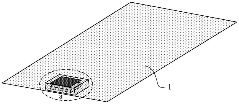
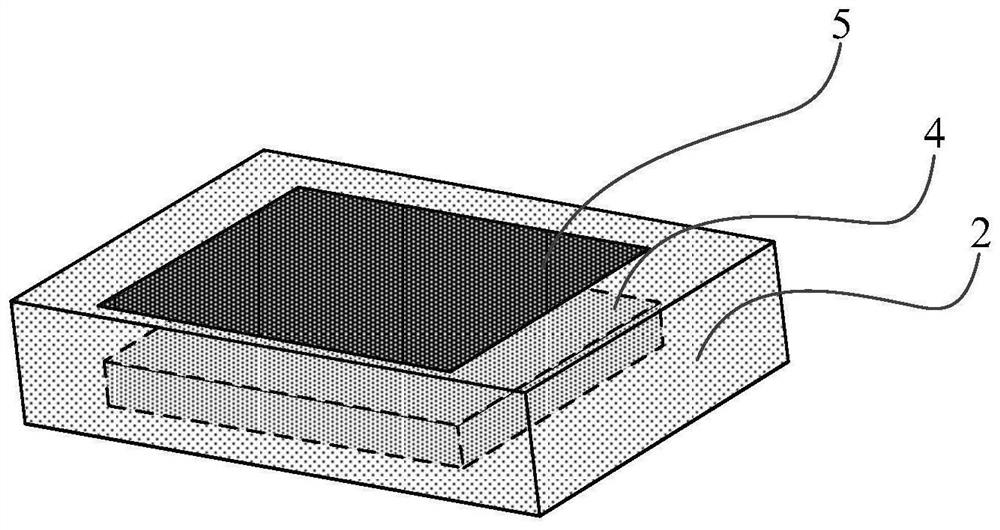
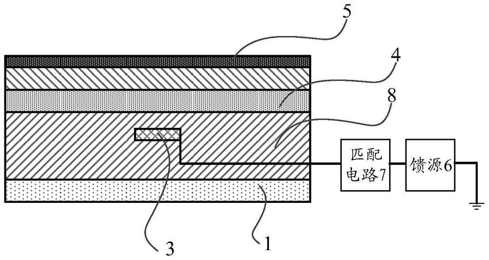
[0022] figure 1 A schematic diagram of the internal structure of an electronic device according to an embodiment of the present application is illustrated, figure 2 A schematic diagram illustrating area a of the internal structure of an electronic device according to an embodiment of the present application, image 3 A schematic diagram of an internal cross-sectional structure of an electronic device according to an embodiment of the present application is illustrated. like figure 1 , figure 2 and image 3 As shown, the electronic device includes: a metal middle frame 1 , a sound cavity housing 2 and a feed source 6 . The sound cavity shell 2 is fixed on the metal middle frame 1. The sound cavity shell 2 is provided with a sound ca...


PUM


Abstract

The application discloses an electronic device, which belongs to the technical field of antennas. The electronic device includes: a metal middle frame, a sound cavity shell, a sound cavity metal body, a sound cavity metal support piece and a feed source. The sound cavity shell is fixed on the metal middle frame, the sound cavity metal body and the sound cavity metal support sheet are arranged in the inner cavity of the sound cavity shell at intervals, and the sound cavity metal body is insulated from the metal middle frame. The feed source is used to feed the excitation signal into the metal body of the sound cavity to excite the metal body of the sound cavity to resonate at the first resonant frequency, and the excitation signal is also coupled to the metal support of the sound cavity through the gap between the metal body of the sound cavity and the metal support plate of the sound cavity plate to excite the metal support plate of the sound cavity to resonate at the first resonant frequency. In the present application, when the feed source feeds the excitation signal to the metal body of the sound cavity, the electronic device can be in the working mode of a microstrip antenna with a working wavelength of 1 / 2, which ensures the efficient radiation and directivity of the electronic device.

Description

technical field [0001] The present application relates to the field of antenna technology, and in particular, to an electronic device. Background technique [0002] At present, in the process of using the electronic equipment, in order to ensure the antenna performance of the electronic equipment, the antenna device is fixedly installed. In order to ensure the rationality of the setting of the antenna device, the metal frame of the electronic device is used as the radiator to set the antenna device. For example, the design scheme of slits at the bottom or both sides of the metal frame can realize the metal frame as a radiator. However, by using the metal frame as a radiator, the radiation efficiency is low, and the radiation pattern is nearly omnidirectional, thereby reducing the antenna performance of the electronic device. SUMMARY OF THE INVENTION [0003] The present application provides an electronic device, which can realize the directivity of the beam radiation dir...

Claims


Application Information

Patent Timeline
Patent Type & Authority Patents(China)
IPC IPC(8): H01Q1/36H01Q1/50H01Q15/14
CPCH01Q1/50H01Q1/36H01Q15/14
Inventor 贾玉虎
Owner GUANGDONG OPPO MOBILE TELECOMM CORP LTD
Why Eureka
Try Eureka