Clamping and feeding device for cable laying in cable trench

A cable laying and feeding device technology, applied in cable installation devices, cable installation, cable laying equipment, etc., can solve the problems of poor laying process effect, decreased work efficiency, slow manual laying speed, etc.

Active Publication Date: 2020-10-20
STATE GRID SHANDONG ELECTRIC POWER CO PINGYUAN POWER SUPPLY CO
View PDF14 Cites 7 Cited by
  • Summary
  • Abstract
  • Description
  • Claims
  • Application Information

AI Technical Summary

Problems solved by technology

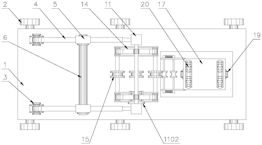
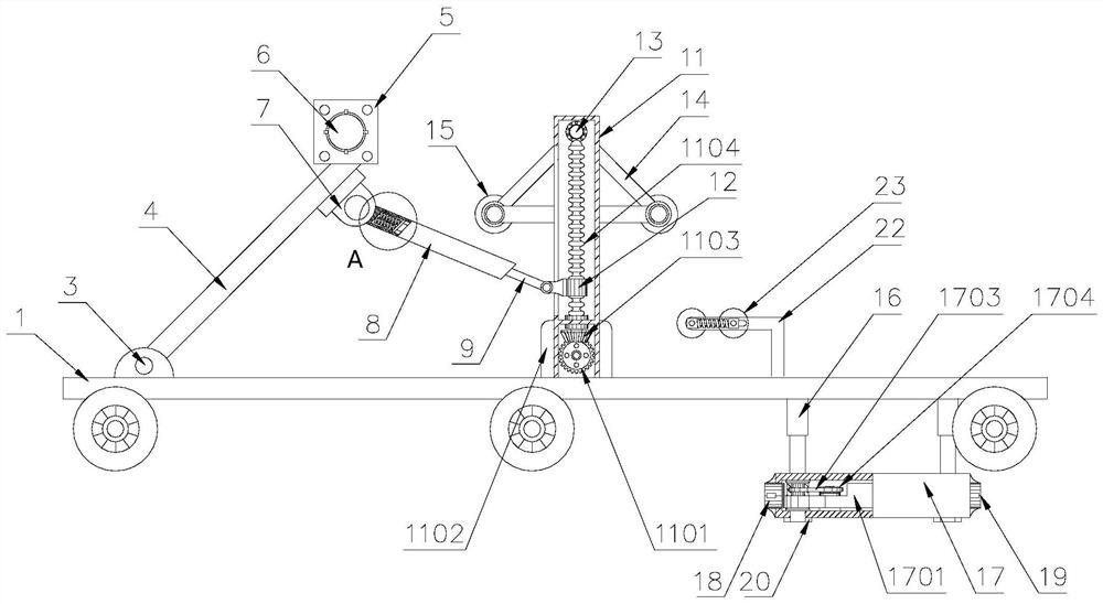
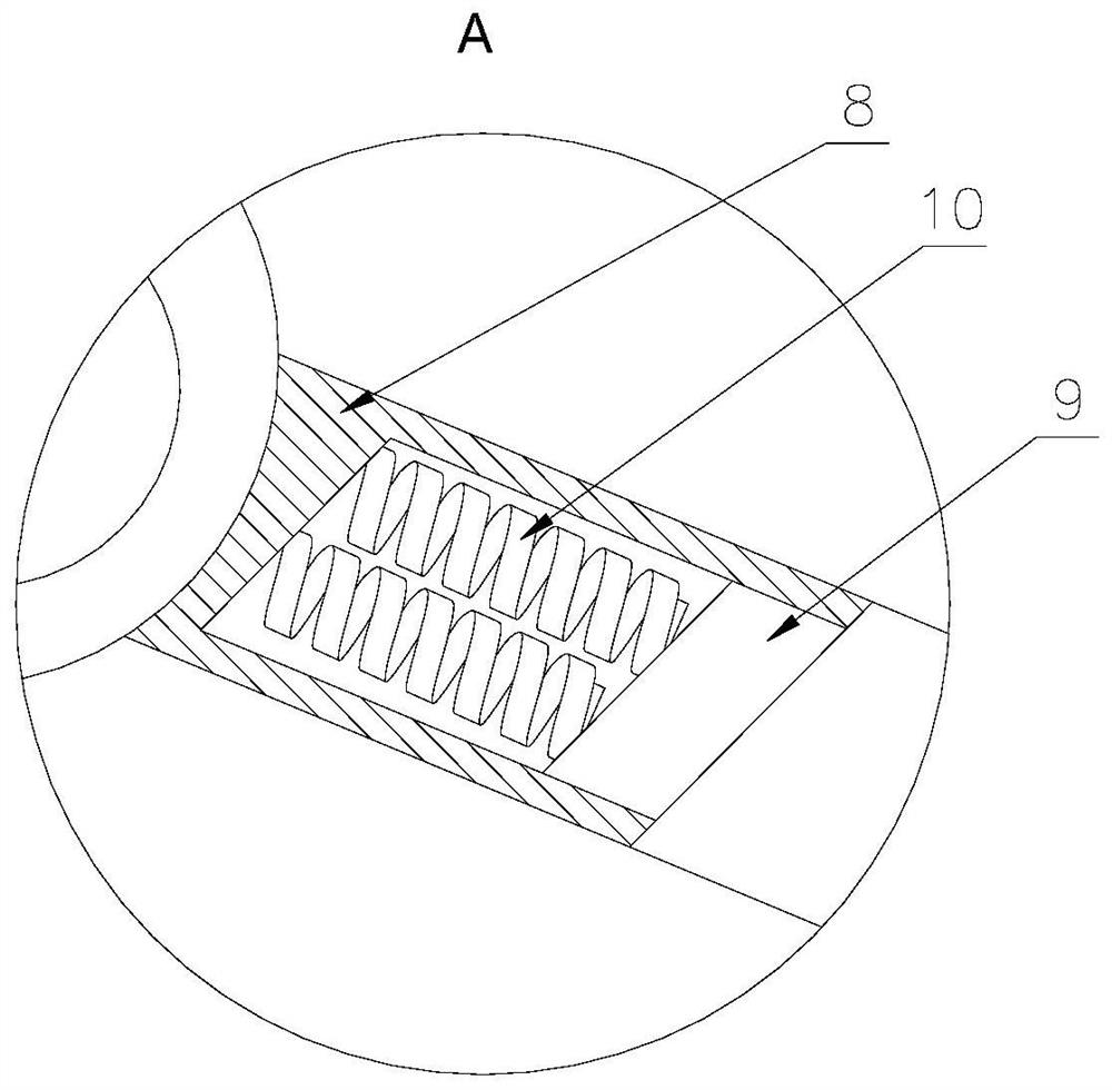
[0004] The purpose of the present invention is to overcome the deficiencies in the prior art and provide a clamping and feeding device for cable laying in cable trenches. When in use, the feeding device is arranged on the upper part of the cable trench, and the

Method used


Image

  • Clamping and feeding device for cable laying in cable trench
  • Clamping and feeding device for cable laying in cable trench
  • Clamping and feeding device for cable laying in cable trench

Examples


Embodiment Construction

[0037] Attached below Figure 1-8 , clearly and completely describe the technical solutions in the embodiments of the present invention, obviously, the described embodiments are only some of the embodiments of the present invention, not all of them. Based on the embodiments of the present invention, all other embodiments obtained by persons of ordinary skill in the art without making creative efforts belong to the protection scope of the present invention.

[0038] In describing the present invention, it should be understood that the terms "longitudinal", "transverse", "upper", "lower", "front", "rear", "left", "right", "vertical", The orientations or positional relationships indicated by "horizontal", "top", "bottom", "inner", "outer", etc. are based on the orientations or positional relationships shown in the drawings, and are only for the convenience of describing the present invention, rather than indicating or It should not be construed as limiting the invention by imply...


PUM


Abstract

The invention discloses a clamping and feeding device for cable laying in cable trench. The device comprises a vehicle plate, supporting rods and a conveying mechanism. The supporting rods are symmetrically installed on the vehicle plate, supporting seats on the two sides are connected through a transverse rod, a notch is formed in the right side of the vehicle plate, and the upper portion of theconveying mechanism is installed on the lower portion of the vehicle plate through a support; the conveying mechanism comprises a shell and servo motors symmetrically arranged in the shell. Two sets of rollers are arranged on each of the two sides in the shell, one end of each roller on the front portion of the shell is connected with a synchronous belt wheel through a synchronous belt, the rollers on the two sides are connected through conveying belts, and a cable enters the transmission mechanism through a feeding port, is arranged between the conveying belts on the two sides, extends out ofthe shell through a discharging port and is arranged in a cable trench. When the clamping and feeding device is used, the feeding device is arranged on the upper portion of a cable trench, cables arelaid in the cable trench through the conveying mechanism, and the problems that in the prior art, the manual laying speed is low, labor intensity is high, and the laying process effect is poor, so that working efficiency is reduced are solved.

Description

technical field [0001] The invention belongs to the technical field of cable laying, in particular to a clamping and feeding device for cable laying in a cable trench. Background technique [0002] Cable trench is an underground pipeline for laying and replacing electric power or telecommunication cable facilities, and is also an enclosure structure for cable facilities. There are rectangular, circular, arched and other pipeline structures. The cable trenches commonly used in domestic power transmission projects are underground Cable trenches, cable tunnels, cable direct burials, cable pipes, cable tunnels and cable direct burials are commonly used. Commonly used cable trenches in substation engineering include cable tunnels, above-ground cable trenches, and underground cable trenches. Cable tunnels are used for power cables, ground and underground cable trenches are used for control cables, and sometimes cables are used locally. [0003] However, most of the existing cabl...

Claims


Application Information

Patent Timeline
IPC IPC(8): H02G1/08
CPCH02G1/081
Inventor 田忠禹张玉龙祖林海周晓曼贾翠庆王超路兴平王瑞宋洪富梁晓
Owner STATE GRID SHANDONG ELECTRIC POWER CO PINGYUAN POWER SUPPLY CO
Why Eureka
Try Eureka