Method for improving working performance of antipodal Vivaldi antenna

A working performance and antenna technology, applied in the fields of electromagnetic fields and microwaves, can solve problems such as waveform smearing, limited antenna operating frequency band, reflected voltage damage, etc., and achieve the goal of eliminating smearing, avoiding ultra-wideband pulse source damage, and optimizing design Effect

Active Publication Date: 2022-02-01
中国人民解放军63660部队
View PDF9 Cites 0 Cited by
  • Summary
  • Abstract
  • Description
  • Claims
  • Application Information

AI Technical Summary

Problems solved by technology

[0007] The purpose of the present invention is to provide a method for improving the working performance of the antipodal Vivaldi antenna, to solve the problem that the antipodal Vivaldi antenna has a limited operating frequency band, and when the antipodal Vivaldi antenna radiates ultra-wide-spectrum high-voltage pulses, the reflected voltage at the feed end is too large and it is easy to cause problems based on solid-state The ultra-wideband pulse source of the switching device causes irreversible damage and affects the service life of the pulse source, and the technical problem of severe waveform tailing when the anti-Vivaldi antenna radiates ultra-wideband time-domain pulse signals

Method used


Image

  • Method for improving working performance of antipodal Vivaldi antenna
  • Method for improving working performance of antipodal Vivaldi antenna
  • Method for improving working performance of antipodal Vivaldi antenna

Examples


Embodiment 1

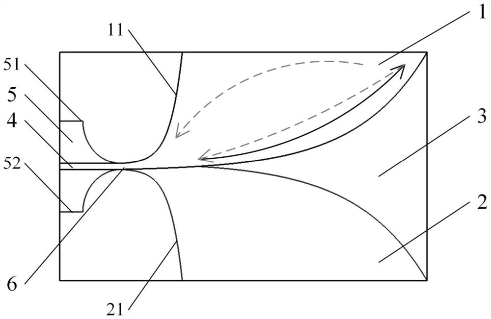
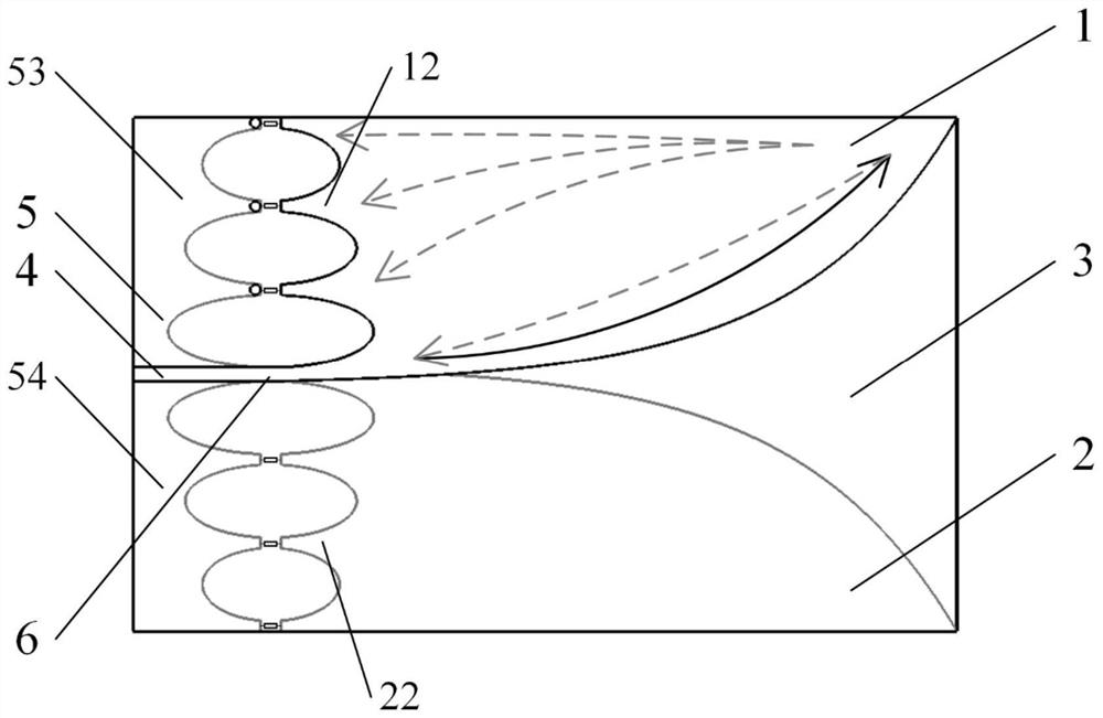
[0049] Such as figure 2 Shown is adopting method provided by the present invention to such as figure 1 An embodiment of a conventional plantar Vivaldi antenna structurally modified and resistively loaded is shown.

[0050] will be like figure 1 The inner exponential gradient line structures 11, 21 of the upper and lower metal radiation patches 1, 2 of the conventional antipodal Vivaldi antenna shown are constructed as figure 2 The upper surface current conducting structure 12 and the lower surface current conducting structure 22 are shown.

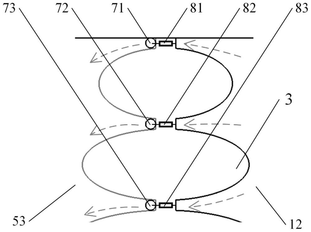
[0051] Such as figure 2 , 3 As shown, the current conduction structure 12 on the upper surface is composed of three planar branches, the outlines of the three planar branches are all elliptic curves, and the starting end is figure 1 The inner exponential gradient line structure 11 of the metal radiation patch 1 on the middle and upper surface gradually narrows in width from the starting end to the end, and the width of the ends of ...

Embodiment 2

[0062] Such as Figure 5 Shown is adopting method provided by the present invention to such as figure 1 An embodiment of a conventional plantar Vivaldi antenna structurally modified and resistively loaded is shown.

[0063] will be like figure 1 The inner exponential gradient line structures 11, 21 of the upper and lower surface metal radiation patches 1, 2 of the conventional antipodal Vivaldi antenna shown are constructed as follows Figure 5 The upper surface current conducting structure 12 and the lower surface current conducting structure 22 are shown.

[0064] Such as Figure 5 As shown, the upper surface current conduction structure 12 is a planar branch, the upper contour line is an exponential gradient line, the lower contour line is an elliptic curve, and the width of the branch gradually narrows from the beginning to the end. Such as Figure 5 As shown, the upper structure of the feed structure microstrip line ground plate is simply transformed into an upper cu...

Embodiment 3

[0068] Such as Figure 7 Shown is adopting method provided by the present invention to such as figure 1 An embodiment of a conventional plantar Vivaldi antenna structurally modified and resistively loaded is shown.

[0069] Such as figure 1 , 7 As shown, an elliptic curve is used to replace the inner exponential gradient line structure 11 of the metal radiation patch 1 on the upper surface of the conventional antipodal Vivaldi antenna to construct the upper surface current conducting structure 12 and the upper side current grounding structure 53 . Similarly, the inner exponential gradient line 12 of the metal radiation patch 2 on the lower surface of the conventional antipodal Vivaldi antenna is constructed as the lower surface current conducting structure 22 and the lower side current grounding structure 54 by using the same elliptic curve. Such as Figure 7 As shown, the positions of the upper surface current conducting structure 12 and the upper side current grounding s...


PUM


Abstract

The invention belongs to the technical field of electromagnetic fields and microwaves, and provides a method for improving the working performance of an antipodal Vivaldi antenna. A current conduction structure and a current grounding structure are constructed on one side of an antenna feed end, and resistance loading is carried out to connect the current conduction structure and the current grounding structure, so that a grounding loop for antenna reflection current is formed, and the working performance of the antenna is improved. Based on the method provided by the invention, the reflection current of the antipodal Vivaldi antenna can be obviously absorbed, so that the reflection voltage of the feed end when the antenna radiates the ultra-wide-spectrum electromagnetic pulse is effectively reduced, the technical risks and problems that an ultra-wide-spectrum pulse source is damaged, the service life is shortened and the like caused by overlarge reflection voltage can be avoided, and the radiation efficiency of the antenna on the ultra-wide spectrum electromagnetic pulse is ensured to the greatest extent; and meanwhile, secondary reflection of the feed end of the antenna can be reduced, and waveform trailing of a radiation field is effectively eliminated. In addition, the working frequency band lower limit of the antenna can be expanded to a certain extent, and antenna miniaturization is achieved.

Description

technical field [0001] The invention belongs to the technical field of electromagnetic fields and microwaves, and in particular relates to a method for improving the working performance of an antipodal Vivaldi antenna. Background technique [0002] The antipodal Vivaldi antenna is evolved from the coplanar Vivaldi antenna. It has the advantages of wide operating frequency band, high gain, good directivity, simple structure, light weight, and easy processing and integration. Although antipodal Vivaldi antennas have been widely used in various ultra-wideband fields, such as ultra-wideband communication, radar, biological detection, etc., there are still many technical problems: [0003] The operating frequency band of the antipodal Vivaldi antenna is limited. The antipodal Vivaldi antenna adopts the microstrip line-parallel double-wire structure for feeding, which basically solves the limitation of the coplanar Vivaldi antenna microstrip line slot line coupling feeding struct...

Claims


Application Information

Patent Timeline
Patent Type & Authority Applications(China)
IPC IPC(8): H01Q1/38H01Q1/50H01Q9/04
CPCH01Q1/50H01Q1/38H01Q9/0407
Inventor 王彬文宁辉燕有杰成真伯刘启龙张凯悦朱美琪
Owner 中国人民解放军63660部队
Why Eureka
Try Eureka