Low Radar Cross Section Reflectarray Antenna Based on Artificial Surface Plasmons

A technology of artificial surface plasmon and radar scattering cross-section, which is applied in the direction of antennas and electrical components, can solve the problems of limited frequency band range and angular range, affecting antenna radiation performance, and large radar scattering cross-section, so as to achieve high wave transmission efficiency, Effect of low radar cross section and guaranteed radiation efficiency

Active Publication Date: 2021-05-28
XIDIAN UNIV +1
View PDF0 Cites 0 Cited by
  • Summary
  • Abstract
  • Description
  • Claims
  • Application Information

AI Technical Summary

Problems solved by technology

[0004] In order to increase the gain of the antenna, the most common method is to increase the radiation aperture of the antenna. Therefore, the existing high-gain antenna usually has the characteristics of a large area, which leads to a large radar cross-section of the antenna. At present, the reduction of the radar cross-section of the antenna is achieved. Methods include shaping the antenna structure, using radar absorbing materials, and using additional frequency-selective surfaces as radomes. Although the existing methods can reduce the radar cross-section of the antenna to a certain extent, the reduced frequency band range and angular domain range is still limited, in addition, many methods of reducing the radar cross section of the antenna will affect the radiation performance of the antenna and reduce the efficiency of the antenna

Method used


Image

  • Low Radar Cross Section Reflectarray Antenna Based on Artificial Surface Plasmons
  • Low Radar Cross Section Reflectarray Antenna Based on Artificial Surface Plasmons
  • Low Radar Cross Section Reflectarray Antenna Based on Artificial Surface Plasmons

Examples


Embodiment 1

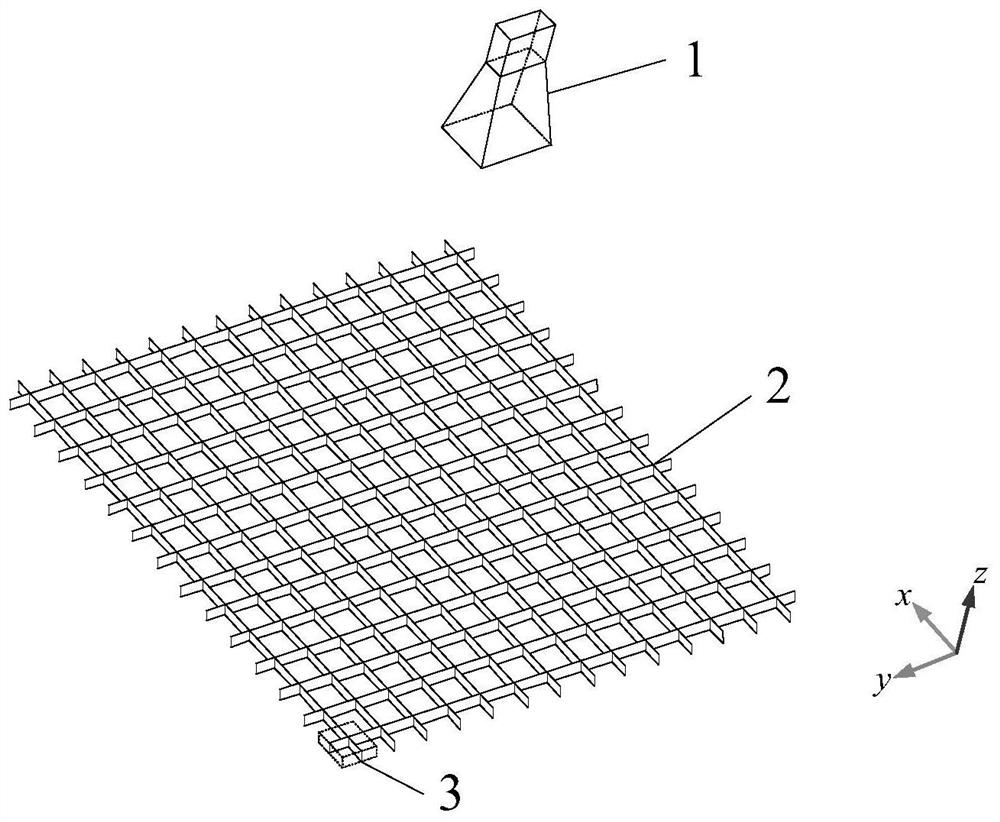
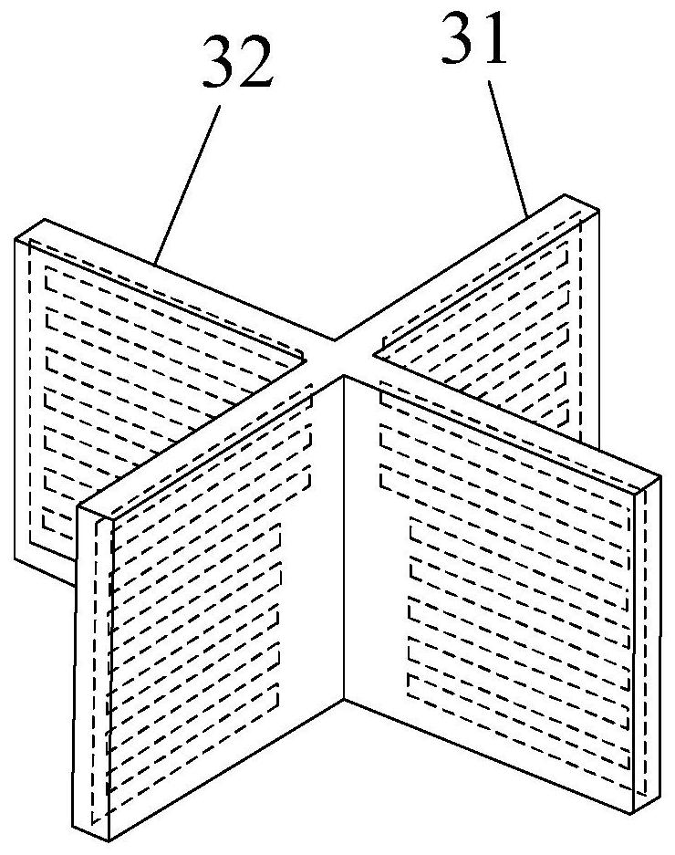
[0036] This embodiment includes a feed 1 and a reflection front 2, wherein the beamwidth of the feed 1 is 40°, the reflection front 2 is located directly below the feed 1, and the distance between the reflection front 2 and the phase center of the feed 1 is f is 165.0 mm, and the reflection front 2 is composed of 14×14 reflection units 3 with the same structure and different parameters. Each reflection unit 3 is composed of a first laminated dielectric plate 31 and a second laminated dielectric plate 32 crossed to form a three-dimensional artificial surface plasmon structure, such as figure 2 shown.

[0037]The reflection phase of each reflection unit 3 in the reflection front 2 is determined by the following formula:

[0038]

[0039] Among them, φ i is the reflection phase of the i-th reflection unit 3, where the value of i is from 1 to 14×14, the working wavelength λ in free space is 30.0mm, R i is the distance from the phase center of the feed 1 to the center of the...

Embodiment 2

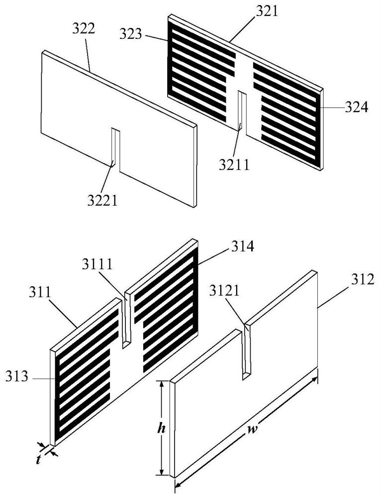
[0050] The structure of this embodiment is the same as that of Embodiment 1, only the following parameters have been adjusted: the beam width of the feed source 1 is 35°, the distance f from the phase center of the feed source 1 to the reflection front 2 is 188.0mm, and the upper metal The width of the three metal patches of the branch 3131 and the width b of the five metal patches of the lower metal branch 3132 are both 0.7mm, the distance between the three metal patches of the upper metal branch 3131 and the five metal patches of the lower metal branch 3132 The distance between the patches and the distance g between the upper metal branch 3131 and the lower metal branch 3132 are all 0.7mm, the width b and height 8×b+7×g of the metal branch 3133 are 0.7mm and 10.5mm respectively, and the first dielectric substrate 311. The heights h of the second dielectric substrate 312, the third dielectric substrate 321, and the fourth dielectric substrate 322 are all 11.2 mm, the first upp...

Embodiment 3

[0053] The structure and parameters of this embodiment are the same as those of Embodiment 1, except that a metal plate with a size of 238 mm×238 mm is added below the reflection front 2 of Embodiment 1, and the metal plate is close to the reflection front 2 .


PUM


Abstract

The invention proposes a low radar scattering cross-section reflection array antenna, which mainly solves the problems of the existing radar scattering cross-section reduction frequency band and narrow angle range of the reflection array antenna. It includes a feed source (1) and a reflection front (2) located below the feed source, the reflection front includes M×N reflection units (3) with the same structure and different parameters, each reflection unit includes four dielectric substrates And the metal surface printed on each medium substrate, each metal surface is composed of upper and lower metal branches and metal branches, wherein the upper metal branch is composed of three metal patches, and the lower metal branch is composed of five metal patches Composition, four dielectric substrates are laminated in pairs to form two laminated dielectric substrates (31, 32), and the two laminated dielectric substrates are placed vertically to form a cross-shaped structure. While ensuring the radiation efficiency of the reflection array antenna, the invention realizes the reduction of the radar scattering section in the range of wide frequency band and wide angle domain, and can be used in various long-distance wireless communication systems.

Description

technical field [0001] The invention belongs to the field of electromagnetic field and microwave technology, and in particular relates to a reflective array antenna with a low radar scattering cross section, which can be used in various long-distance wireless communication systems. Background technique [0002] Surface plasmon SSP is an electromagnetic oscillation formed by the interaction of free electrons and photons in the surface area of ​​a metal, and it is a surface electromagnetic wave that propagates along the interface between the metal and the medium. In the microwave or terahertz frequency range, metals cannot excite surface plasmons, and artificially designed periodic structures can support surface waves with a dispersion relationship similar to surface plasmons. This kind of surface waves is called artificial surface plasmons. Plasmon SSPP, and this periodic structure is called artificial surface plasmon structure. The artificial surface plasmon structure workin...

Claims


Application Information

Patent Timeline
Patent Type & Authority Patents(China)
IPC IPC(8): H01Q15/00
CPCH01Q15/0013H01Q15/0026
Inventor 姜文蒋鹏龚书喜艾夏程通杨大慰
Owner XIDIAN UNIV
Why Eureka
Try Eureka