Dual-polarized slotted waveguide antenna based on stepped four-ridge transition
An open-ended waveguide antenna and dual-polarization technology, applied in the directions of antenna coupling, waveguide opening, antenna grounding device, etc., can solve the problems of high maximum standing wave ratio, increased measurement error, poor in-band matching, etc., to ensure input Port isolation, reducing the deterioration of standing wave ratio, and improving the effect of in-band matching characteristics
- Summary
- Abstract
- Description
- Claims
- Application Information
AI Technical Summary
Problems solved by technology
Method used
Image
Examples
Embodiment 1
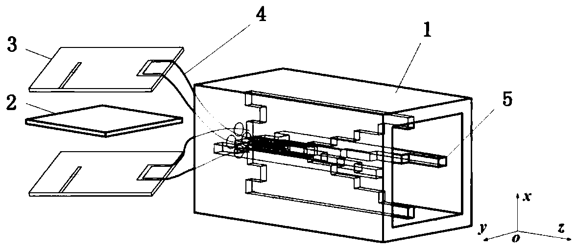
[0032] refer to figure 1 , a dual-polarized apertured waveguide antenna based on a stepped four-ridge transition, including an apertured waveguide 1, a shielded metal plate 2, a microstrip balun 3, a feeding coaxial line 4, and a ridge plate 5;
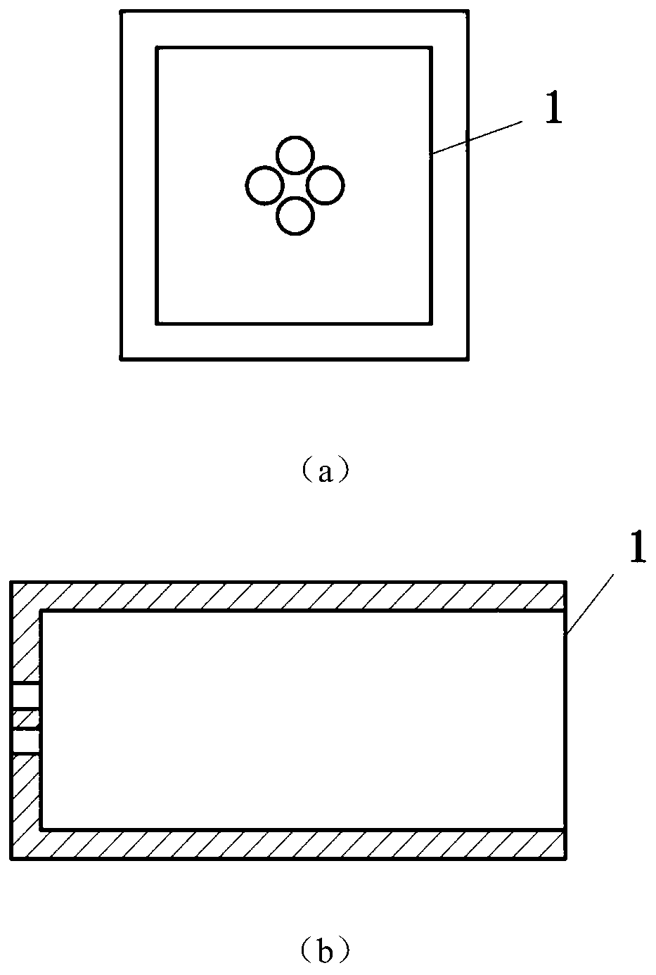
[0033] The open waveguide 1 adopts a square waveguide structure with one end open and one end closed, and the structure of the closed end is as follows: figure 2 As shown in (a), the side length of its cross section is equal to the length of the long side of the WR90 standard rectangular waveguide, and four round holes are opened at its closed end, which are used to connect the spine board 5 and the microstrip balun 3 by the coaxial line Channels are provided, four through holes are symmetrical about the central axis of the open waveguide 1 and are 2.5 mm away from the central axis, the radius of the circular holes is 1.5 mm, and the longitudinal section of the open waveguide 1 is shown in figure 2 As shown in (b), the length of th...
Embodiment 2
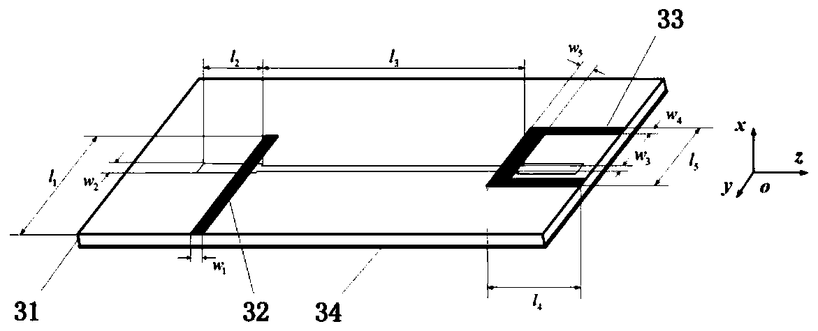
[0038] The structure of this embodiment is the same as that of Embodiment 1, only for the minimum distance d between each pair of ridges 5 of the four pairs of ridges 5 facing each other, the thickness t of the ridges 5, and the step number N of the step change section 51 , the length l of the input microstrip line 32 1 and width w 1 , the length l of the two ends of the dumbbell-shaped gap of the metal floor 34 2 , width w 2 , the length in the middle of the gap l 3 , width w 3 and the length l of the output microstrip line 33 parallel to the Z-axis 4 , width w 4 , the length l of the part perpendicular to the Z axis 5 , with a width of w 5 Made adjustments:
[0039] The minimum distance d=0.6mm between each pair of ridge plates 5; the thickness t=1mm of the ridge plate 1; the number of steps in the step change section 51 N=3, and the step spacing of the ridge plate pairs along the positive direction of the Z axis in turn Increase, the length of the ridge plate paral...
Embodiment 3
[0041] The structure of this embodiment is the same as that of Embodiment 1, only for the minimum distance d between each pair of ridges 5 of the four pairs of ridges 5 facing each other, the thickness t of the ridges 5, and the step number N of the step change section 51 , the length l of the input microstrip line 32 1 and width w 1 , the length l of the two ends of the dumbbell-shaped gap of the metal floor 34 2 , width w 2 , the length in the middle of the gap l 3 , width w 3 and the length l of the output microstrip line 33 parallel to the Z-axis 4 , width w 4 , the length l of the part perpendicular to the Z axis 5 , with a width of w 5 Made adjustments:
[0042] The minimum distance d=3mm between each pair of ridges 5; the thickness t=5mm of the ridges 5; the number of steps in the step change section 51 N=8, and the step spacing of the ridges in the positive direction of the Z axis increases sequentially , the length of the ridge plate parallel to the Z-axis × ...
PUM
 Abstract
Description
Claims
Application Information
 - R&D
- Intellectual Property
- Life Sciences
- Materials
- Tech Scout
- Unparalleled Data Quality
- Higher Quality Content
- 60% Fewer Hallucinations
Browse by: Latest US Patents, China's latest patents, Technical Efficacy Thesaurus, Application Domain, Technology Topic, Popular Technical Reports.
© 2025 PatSnap. All rights reserved.Legal|Privacy policy|Modern Slavery Act Transparency Statement|Sitemap|About US| Contact US: help@patsnap.com


