Microwave single-pole multi-throw switch

A single-pole multi-throw switch, microwave technology, applied in electronic switches, waveguide devices, electrical components and other directions, can solve the problems of poor input and output standing wave index, large insertion loss and so on

Active Publication Date: 2014-03-05
NO 55 INST CHINA ELECTRONIC SCI & TECHNOLOGYGROUP CO LTD
View PDF5 Cites 11 Cited by
  • Summary
  • Abstract
  • Description
  • Claims
  • Application Information

AI Technical Summary

Problems solved by technology

[0003] Due to the defects of circuit topology design, layout design, material selection and process realization, similar products have the following shortcomings: 1) The input and output standing wave indicators are poor; 2) The insertion loss is large, etc.

Method used


Image

  • Microwave single-pole multi-throw switch
  • Microwave single-pole multi-throw switch
  • Microwave single-pole multi-throw switch

Examples


Embodiment 1

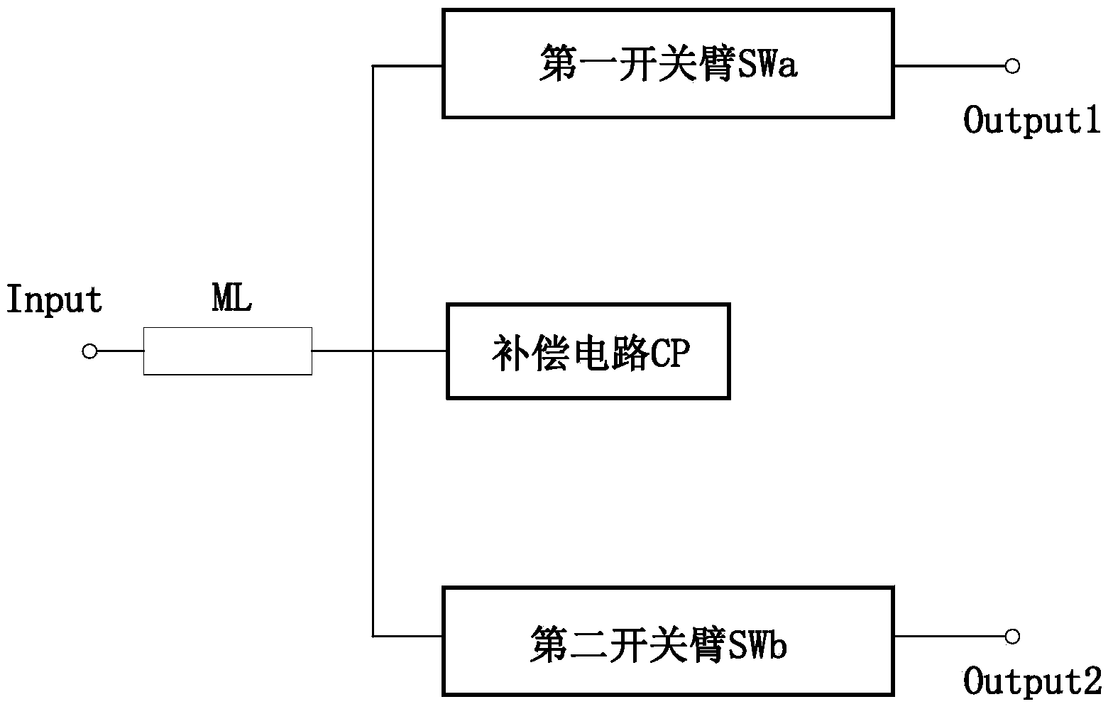
[0021] Example 1: Such as figure 1 As shown, in this embodiment, one end of the input microstrip line ML is the input end Input, and the other end is the common end. The common terminal is also connected to the first switch arm SWa, the second switch arm SWb and the compensation circuit CP. The first switch arm SWa and the second switch arm SWb constitute a switch group. The other end of the first switch arm SWa is the first output terminal Output1, and the other end of the second switch arm SWb is the second output terminal Output2.

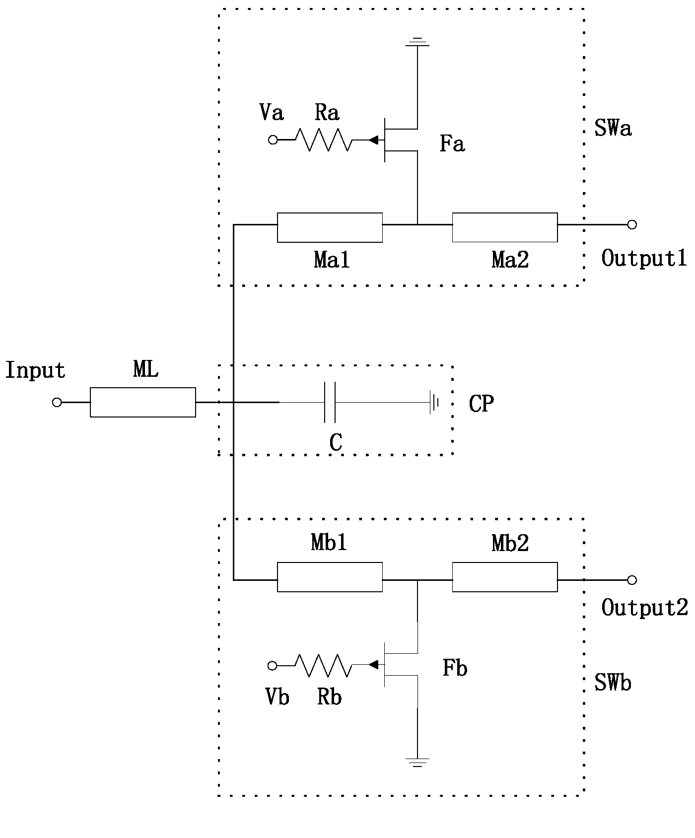
[0022] Such as figure 2 As shown, the first switch arm SWa is composed of a first output microstrip line Ma1, a second output microstrip line Ma2, and a first control NMOS transistor Fa. One end of the first output microstrip line Ma1 is connected to the common end, and the other end is connected to the second output microstrip line Ma2. The other end of the second output microstrip line Ma2 is the first output terminal Output1. The common term...

Embodiment 2

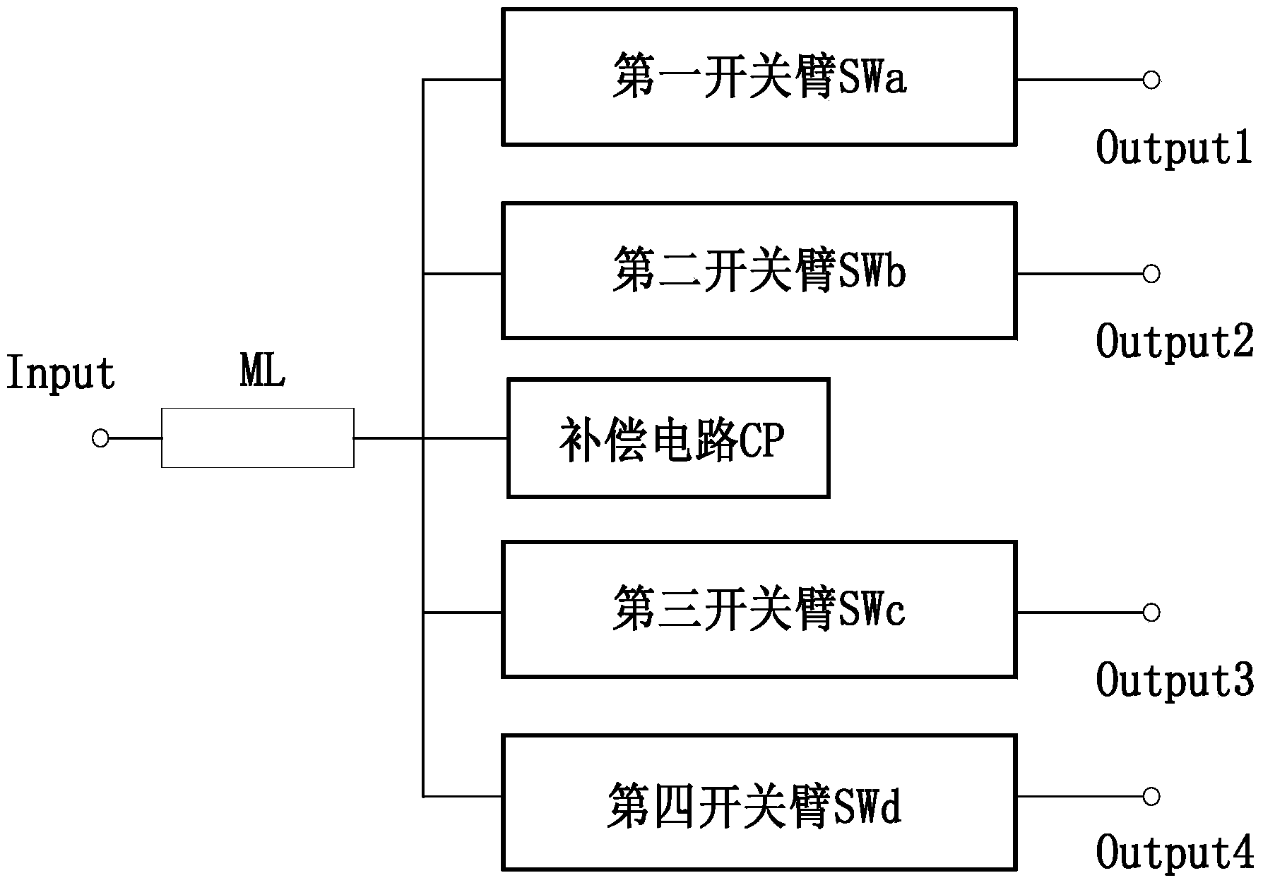
[0026] Embodiment 2: On the basis of Embodiment 1, the switch group can also include more switch arms to realize one end input and multiple output outputs. Such as image 3 As shown, in this embodiment, one end of the input microstrip line ML is the input end Input, and the other end is the common end. The common terminal is also connected to the first switch arm SWa, the second switch arm SWb, the third switch arm SWc, the fourth switch arm SWd, and the compensation circuit CP. The first switch arm SWa, the second switch arm SWb, the third switch arm SWc, and the fourth switch arm SWd constitute a switch group. The other end of the first switch arm SWa is the first output terminal Output1, the other end of the second switch arm SWb is the second output terminal Output2, the other end of the third switch arm SWc is the third output terminal Output3, and the fourth switch arm SWd The other end of is the fourth output terminal Output4.

[0027] Among them, the first switch arm SW...

Embodiment 3

[0030] Example 3: Such as image 3 As shown, in this embodiment, one end of the input microstrip line ML is the input end Input, and the other end is the common end. The common terminal is also connected to the first switch arm SWa, the second switch arm SWb, the third switch arm SWc, the fourth switch arm SWd, and the compensation circuit CP. The first switch arm SWa, the second switch arm SWb, the third switch arm SWc, and the fourth switch arm SWd constitute a switch group. The other end of the first switch arm SWa is the first output terminal Output1, the other end of the second switch arm SWb is the second output terminal Output2, the other end of the third switch arm SWc is the third output terminal Output3, and the fourth switch arm SWd The other end of is the fourth output terminal Output4.

[0031] In this embodiment, the compensation circuit CP is such as Figure 8 As shown, the compensation inductor L and the compensation capacitor C are connected in parallel between ...


PUM


Abstract

The invention discloses a microwave single-pole multi-throw switch which comprises an input transmission line. One end of the input transmission line serves as an input end, the other end of the input transmission line at the same time is connected to a switch group and a compensating circuit; the switch group is composed of at least two switch arms, and the other end of each switch arm serves as an output end; and the compensating circuit changes an input impedance of the switch group, so that the switch group and the input transmission line are matched in terms of the impedance. In the invention, based on a single-pole double-throw switch, a plurality of switch arms adds to constitute the single-pole multi-throw switch. At the same time, the plurality of switch arms are connected in parallel with the compensating circuit, and the compensating circuit is composed of a reactive component capacitor and / or an inductor group. When the microwave single-pole multi-throw switch is in actual use, the inductor and capacitor in the compensating circuit is enabled to choose the appropriate capacitance and inductance values, so as to realize the impedance matching between the switch arms and the input source and the input transmission line.

Description

Technical field [0001] The invention relates to a microwave single-pole multi-throw switch, which belongs to the field of microwave control devices. Background technique [0002] The single-pole double-throw switch is a microwave control device mainly used in microwave communications, radar, electronic countermeasures, and satellite aerospace systems. Because the compensated single-pole double-throw switch based on the field effect tube has the advantages of wide operating frequency range, small size, light weight, fast switching speed, no power consumption, and high reliability, it is widely used in many modern advanced electronic systems and equipment. welcome. The parameters and main technical indicators describing the performance of this product are: 1) working frequency bandwidth; 2) insertion loss; 3) isolation; 4) input and output standing waves; 5) switching speed; 6) chip size; 7) chip Consistency in electrical performance. [0003] Similar products have the following s...

Claims


Application Information

Patent Timeline
Patent Type & Authority Applications(China)
IPC IPC(8): H03K17/56H01P1/10H01P1/15
Inventor 沈宏昌李思其任春江韩群飞
Owner NO 55 INST CHINA ELECTRONIC SCI & TECHNOLOGYGROUP CO LTD
Why Eureka
Try Eureka