Multilayered structure integrated filter antenna based on filter Balun

A filter antenna and multi-layer structure technology, which is applied in the direction of antenna, antenna grounding device, radiation element structure, etc., can solve the problem that the miniaturization requirements of microwave devices cannot be well met, the radiator is not used as a filter, and the size of the filter antenna is large and other issues, to achieve the effect of improving bandwidth, small overall size, and expanding bandwidth

Inactive Publication Date: 2018-11-13
XIDIAN UNIV
View PDF4 Cites 13 Cited by
  • Summary
  • Abstract
  • Description
  • Claims
  • Application Information

AI Technical Summary

Problems solved by technology

[0007] In 2015, J.Shi and X.Wu published "A Compact Differential Filtering Quasi-Yagi Antenna With High Frequency Selectivity and Low Cross -PolarizationLevels", the paper proposes a differential quasi-Yagi antenna with filter response, but the radiator does not have a resonator as a filter, which is not conducive to reducing size and loss
[0008] In 2015, C.X.Mao and S.Gao et al published "Integrated Filtering Antenna with Controllable Frequency Bandwidth" in IEEE Transactions Antennas and Propagation journal (Vol.63, No.12, 2015, pp.5492–5499.), in the paper The integrated design of the filter and antenna widens the bandwidth, improves the frequency selectivity and obtains a flatter gain, however, an additional filter circuit is introduced into the antenna feed network, resulting in increased insertion loss
[0009] In 2016, Tang.H and Chen J.X et al. published "Integration design of filtering antenna with load-insensitive balun filter" in IEEE Transactions on Components Packaging & Manufacturing Technology (No.6, 2016, pp.1408-1416.). The paper uses a single However, when the working frequency band is low, the size of the designed filter antenna will be relatively large, resulting in a large volume of the entire system, which cannot well meet the increasingly stringent requirements of microwave devices. miniaturization requirements

Method used


Image

  • Multilayered structure integrated filter antenna based on filter Balun
  • Multilayered structure integrated filter antenna based on filter Balun
  • Multilayered structure integrated filter antenna based on filter Balun

Examples


Embodiment 1

[0031] Embodiment 1, a multi-layer structure integrated filter antenna based on a filter balun working at 2.45 GHz.

[0032] refer to figure 1 , this example includes a filtering part 1 , a substrate part 2 and a radiation unit 3 . Among them: the substrate part 2 is composed of two layers of dielectric substrates 21, 22, and a metal floor 23; the radiation unit 3 is composed of two λ / 2 microstrip lines 31, 32, two butterfly-shaped printed dipoles 33, 34 and a director 35 composition. Filter part 1 is made up of input port microstrip line 11, output port microstrip line 12, 13 and filtering balun 14, and this filtering balun 14 is made up of two face-to-face C-shaped λ / 2 second-order ladder impedance resonators 141, 142 and two back-to-back C-shaped λ / 2 second-order ladder impedance resonators 143 and 144.

[0033] Input port microstrip line 11, output port microstrip line 12, 13, two half-wavelength microstrip lines 31, 32, first C-shaped λ / 2 second-order ladder impedance ...

Embodiment 2

[0047] Embodiment 2, a multi-layer structure integrated filter antenna based on a filter balun working at 2.16 GHz.

[0048] refer to figure 1 , the structure of this example is the same as that of Example 1, and its parameters are set as follows:

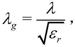
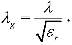
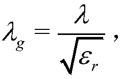
[0049] Dielectric constant ε r =4.5, the vertical length of the butterfly-shaped printed dipole is 26mm, the length of the short side is 5.2mm, and the length of the long side is 10mm. The two λ / 4 microstrip lines 31 and 32 of the radiation unit have the same size, the width is the same as the width parameter given in Embodiment 1, and the lengths are λ g / 4, where λ is the working wavelength.

[0050] The input port microstrip lines constituting the filter part, two output port microstrip lines, two face-to-face C-shaped λ / 2 second-order ladder impedance resonators and two back-to-back C-shaped λ / 2 second-order ladders of the filter balun The dimensions of the impedance resonators are the same as the parameters given in Embo...

Embodiment 3

[0052] Embodiment 3, a multi-layer structure integrated filter antenna based on a filter balun working at 1.68 GHz.

[0053] refer to figure 1 , the structure of this example is the same as that of Example 1, and its parameters are set as follows:

[0054] Dielectric constant ε r =7.5, the vertical length of the butterfly-shaped printed dipole is 28mm, the length of the short side is 5.4mm, and the length of the long side is 10.4mm. The two λ / 4 microstrip lines 31 and 32 of the radiation unit have the same size, the width is the same as the width parameter given in Embodiment 1, and the length is λ g / 4, where λ is the working wavelength.

[0055] The input port microstrip line that constitutes the filtering part, two output port microstrip lines and two face-to-face C-shaped λ / 2 second-order ladder impedance resonators and two back-to-back C-shaped λ / 2 second-order ladders of the filter balun The dimensions of the impedance resonators are the same as the parameters give...


PUM


Abstract

The invention discloses a multilayered structure integrated filter antenna based on a filter Balun, and mainly solves the problem that the volume of the filter antenna of a traditional monolayer micro-strip structure is larger. The multilayered structure integrated filter comprises a dielectric substrate, a filter part and a radiation unit, wherein the dielectric substrate comprises two micro-strip dielectric substrates and a metal ground; the filter part comprises an input port, the filter Balun positioned on the left sides of the dielectric substrates and two output ports connected with thefiler part; the filter Balun comprises two face-to-face C-shaped second-order stepped impedance resonators etched on the upper dielectric substrate and two back-to-back C-shaped second-order stepped impedance resonators etched on the upper surface of the lower dielectric substrate; the radiation unit is etched on the upper surface of the upper dielectric substrate, and comprises two micro-strip lines, two butterfly printing dipoles and a director. The multilayered structure integrated filter antenna has the advantages of compact structure, wide bandwidth, high frequency edge selectivity and good out-of-band rejection, and can be used for the radio frequency front end of a wireless communication system.

Description

technical field [0001] The invention belongs to the technical field of microwave devices, and in particular relates to a multi-layer structure integrated filter antenna, which can be used for a radio frequency front end of a wireless communication system. Background technique [0002] In recent years, the development of wireless communication technology has become more and more rapid, people have higher and higher requirements for the performance and volume of communication systems, and the performance of microwave communication components is becoming more and more multifunctional and integrated. , The appearance is also more and more towards the direction of miniaturization and portability. [0003] The wireless communication system is composed of three parts: sending equipment, receiving equipment and wireless channels, and uses wireless electromagnetic waves to realize information and data transmission systems. It is classified according to the working frequency band or ...

Claims


Application Information

Patent Timeline
Patent Type & Authority Applications(China)
IPC IPC(8): H01Q23/00H01Q1/48H01Q19/30H01Q1/50H01Q1/38
CPCH01Q1/38H01Q1/48H01Q1/50H01Q19/30H01Q23/00
Inventor 吴边张楠张亚辉许梅李镇宁夏磊
Owner XIDIAN UNIV
Why Eureka
Try Eureka