Antenna structure, transponder and method of manufacturing an antenna structure

A technology of antenna structure and coupling structure, which is applied in the direction of antenna, mid-position feeding between antenna endpoints, resonant antenna, etc.

Active Publication Date: 2008-07-30
NXP BV
View PDF0 Cites 12 Cited by
  • Summary
  • Abstract
  • Description
  • Claims
  • Application Information

AI Technical Summary

Problems solved by technology

Systems with operating frequencies below about 800MHz are usually based on inductive coupling of coils, with the help of capacit

Method used


Image

  • Antenna structure, transponder and method of manufacturing an antenna structure
  • Antenna structure, transponder and method of manufacturing an antenna structure
  • Antenna structure, transponder and method of manufacturing an antenna structure

Examples


Embodiment Construction

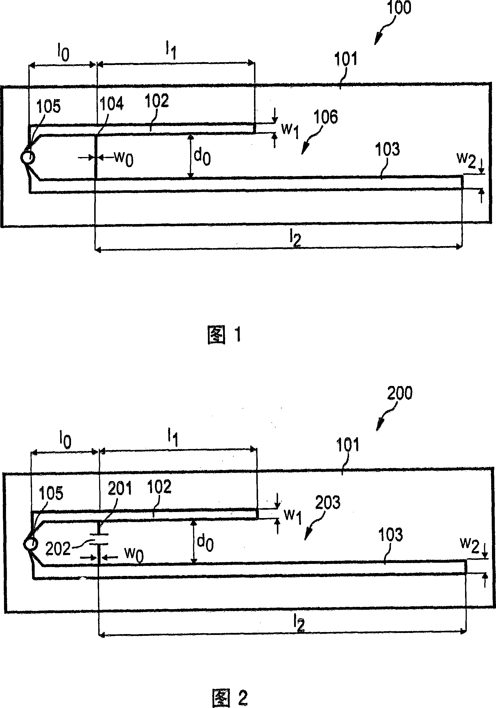
[0067]Hereinafter, referring to FIG. 1, the RFID tag 100 according to the first exemplary embodiment of the present invention will be described. The RFID tag 100 includes a plastic substrate 101, an antenna structure 106 provided on the plastic substrate 101, and an integrated circuit (IC) 105.

[0068] The antenna structure 106 includes a first conductive element 102 having a first end and a second end. In addition, a second conductive element 103 is provided, which has a first end and a second end. An IC 105 is connected between the first end of the first conductive element 102 of the antenna structure 106 and the first end of the second conductive element 103. An ohmic shorting element 104 is provided, that is, another electrical connection element for connecting the first conductive element 102 and the second conductive element 103 into a circuit. The ohmic shorting element 104 is connected to the first ends of the conductive elements 102 and 103. The conductive elements 102 a...


PUM


Abstract

An antenna structure (106) comprising a first electrically conductive element (102) having a first end and a second end, a second electrically conductive element (103) having a first end and a second end, and a coupling structure (104) short- circuiting the first electrically conductive element (102) with the second electrically conductive element (103) by means of electrically connecting the electrically conductive elements (102, 103) at positions between the first and the second ends, wherein an integrated circuit (105) is connectable between the first end of the first electrically conductive element (102) and the first end of the second electrically conductive element (103).

Description

Technical field [0001] The invention relates to an antenna structure. [0002] In addition, the present invention relates to a transponder. [0003] Finally, the invention relates to a method of manufacturing an antenna structure. Background technique [0004] The importance of automatic identification systems is increasing, especially in the service sector, logistics, commerce, and industrial production. Therefore, automatic identification systems are being increasingly implemented in these and other fields, and will likely replace bar code systems in the future. A further application of the identification system involves the identification of individuals and animals. [0005] In specific non-contact identification systems, such as transponder systems, these systems are suitable for rapid wireless transmission of data without the need for cable connections that may be annoying. These systems utilize the radiation and absorption of electromagnetic waves, especially in the high-fr...

Claims


Application Information

Patent Timeline
IPC IPC(8): G06K19/077H01Q1/22H01Q9/28
CPCH01Q1/22H01Q9/285Y10T29/49016
Inventor 阿希姆·希尔格斯
Owner NXP BV
Why Eureka
Try Eureka