
Apparatus and method for detecting damage to a machine

A kind of equipment and machine technology, applied in the direction of machine/structural component testing, instruments, measuring devices, etc., can solve problems such as structural damage and damage

Inactive Publication Date: 2011-04-06
WACKER NEUSON SE
View PDF0 Cites 11 Cited by
  • Summary
  • Abstract
  • Description
  • Claims
  • Application Information

AI Technical Summary

Problems solved by technology

Due to the intensity of the operating forces that are often accompanied by vibrations, after a certain operating time, damage to the structure can occur that can cause significant further damage or at least undesirably interrupt the working process

Method used


Image

  • Apparatus and method for detecting damage to a machine
  • Apparatus and method for detecting damage to a machine
  • Apparatus and method for detecting damage to a machine

Examples


Embodiment Construction

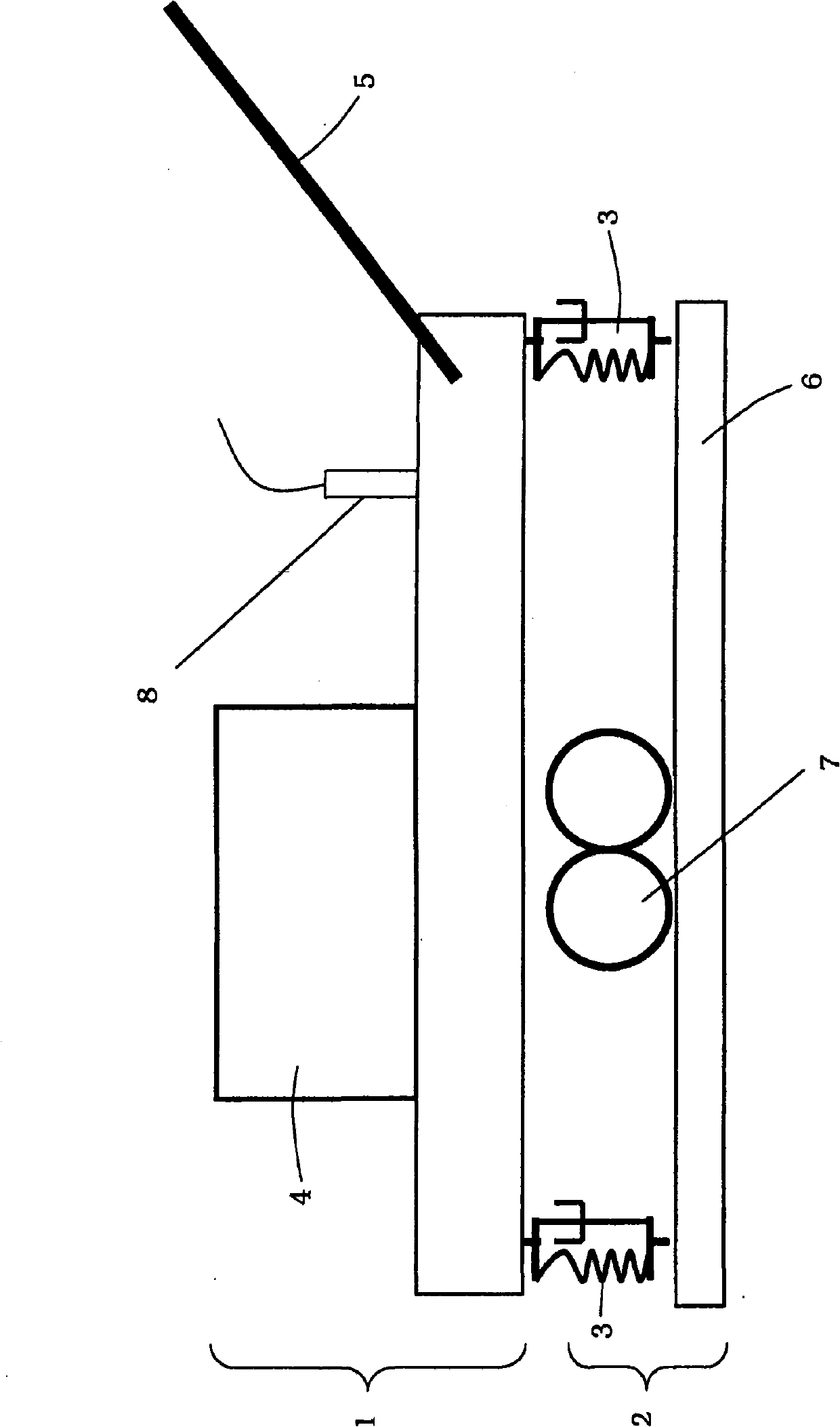
[0045] figure 1 A machine in the form of a construction machine is shown, in this case a vibrating plate. However the device according to the invention may be used in many other types of machines, including construction machines, for timely diagnosis of damage to mechanical parts.

[0046] The vibrating plate has an upper block 1 which is coupled to a lower block 2 via a spring-damping element 3 so that the two blocks can move relative to each other. The upper block 1 comprises a drive motor 4 and a drawbar 5 by which the vibrating plate can be manually guided by the operator. The lower block 2 has a soil contact plate 6 for compacting the soil and a vibration exciter 7 which strikes the soil contact plate 6 and is driven by the drive motor 4 . The vibration exciter 7 may for example consist of two unbalanced shafts which rotate in opposite directions in operative cooperation and generate directional vibrations. However, other excitation possibilities are also known.

[00...


PUM


Abstract

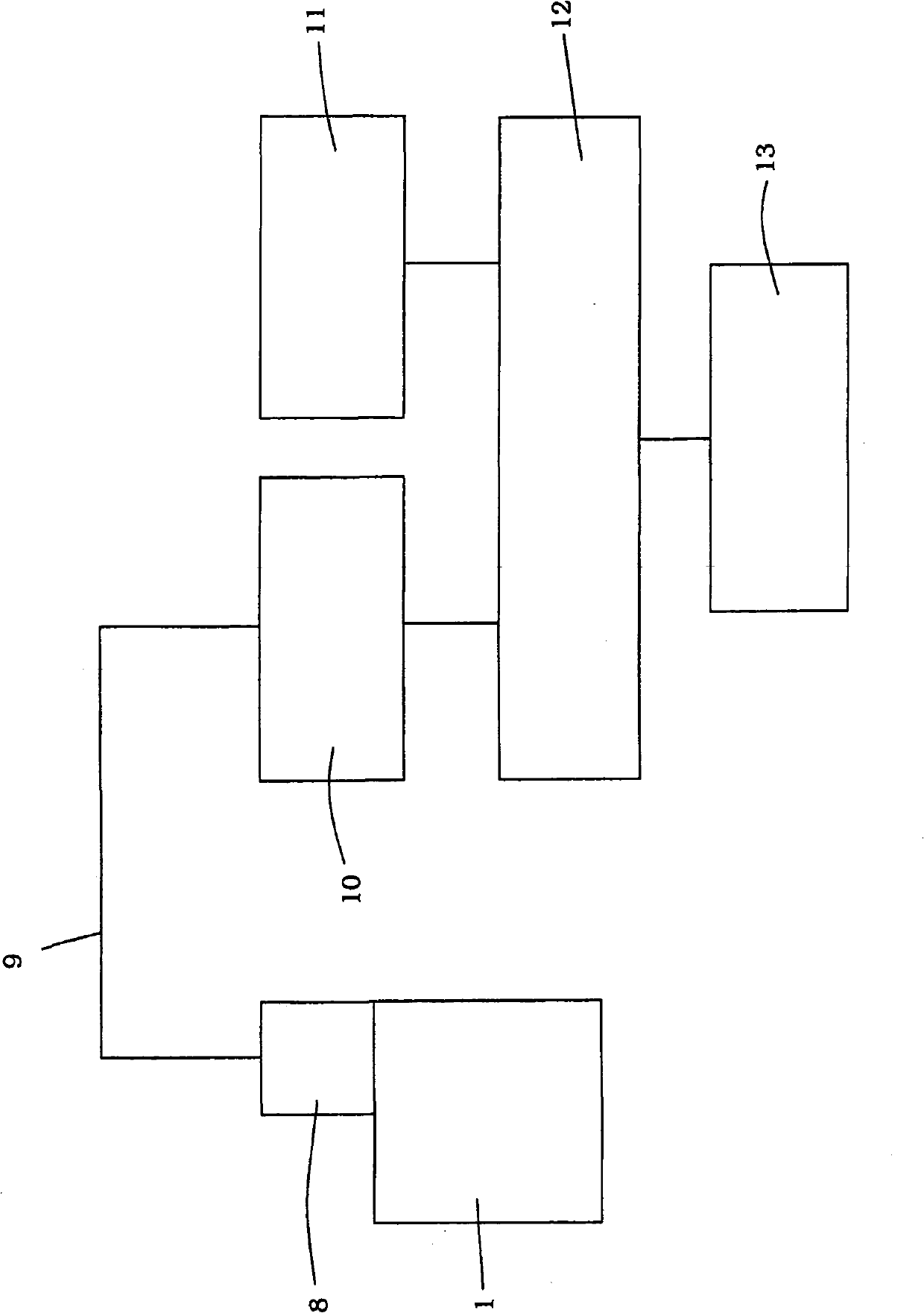
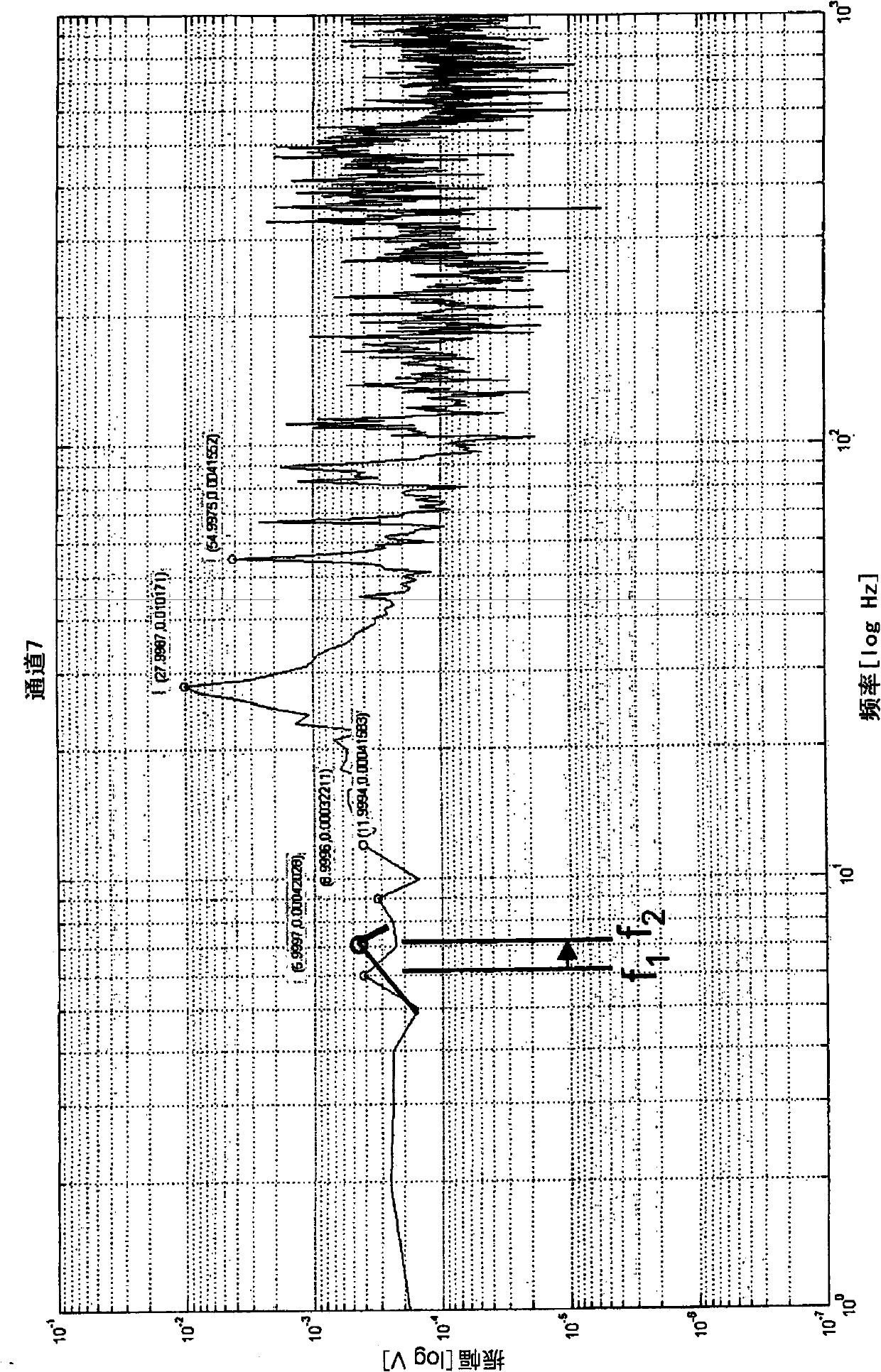
An apparatus for detecting damage to a machine that is excited at a previously known frequency by a vibration exciter (7) has an acceleration sensor (8) for recording a current amplitude spectrum of an upper mass (1). A previously known amplitude spectrum of the upper mass (1) is stored in a memory device (11). The current amplitude spectrum is compared with the previously known amplitude spectrum in a comparison device (12). If the comparison device determines that the spectra differ from one another, a corresponding deviation signal is generated and is output via a display device (13) for informing the operator in order to inform the latter of possible damage.

Description

technical field [0001] The invention relates to devices and methods for detecting damage to machinery. Background technique [0002] Many machines, especially construction equipment such as joint cutters, floor cutting mills, hammers, vibrating plates, vibrating rollers, tampers, etc., are subject to excitation of their structure under the action of operating forces. These machines usually have drives which generate strong vibrations which then create stresses on the machine structure. Especially in vibrating machines such as vibrating plates and vibrating rollers or tampers, these vibrations are desired and serve the purpose of the machine. Due to the intensity of the operating forces, which are often accompanied by vibrations, after a certain operating time, damage to the structure can occur which can lead to significant further damage or at least undesirably interrupt the working process. Therefore, it is desirable to detect component damage that has occurred during mac...

Claims


Application Information

Patent Timeline
Patent Type & Authority Applications(China)
IPC IPC(8): G01M13/00G01M99/00
CPCG01M13/045
Inventor S·瓦格纳
Owner WACKER NEUSON SE
Learn More