Method and device for recognizing bearing damage using oscillation signal analysis

A vibration signal and bearing damage technology, applied to rolling contact bearings, rotating bearings, bearings, etc., can solve problems such as time-consuming, damage, and unrecognizable bearings

Inactive Publication Date: 2011-04-06
SIEMENS AG
View PDF0 Cites 17 Cited by
  • Summary
  • Abstract
  • Description
  • Claims
  • Application Information

AI Technical Summary

Problems solved by technology

This manual setup is time-consuming and should only be performed by previously trained personnel
Possible bearing damage cannot be detected if the limit frequency or damping of the bandpass filter is set incorrectly
If bearing damage is not recognized in time, it can lead to the failure of the entire machine in which the bearing is installed

Method used


Image

  • Method and device for recognizing bearing damage using oscillation signal analysis
  • Method and device for recognizing bearing damage using oscillation signal analysis
  • Method and device for recognizing bearing damage using oscillation signal analysis

Examples


Embodiment Construction

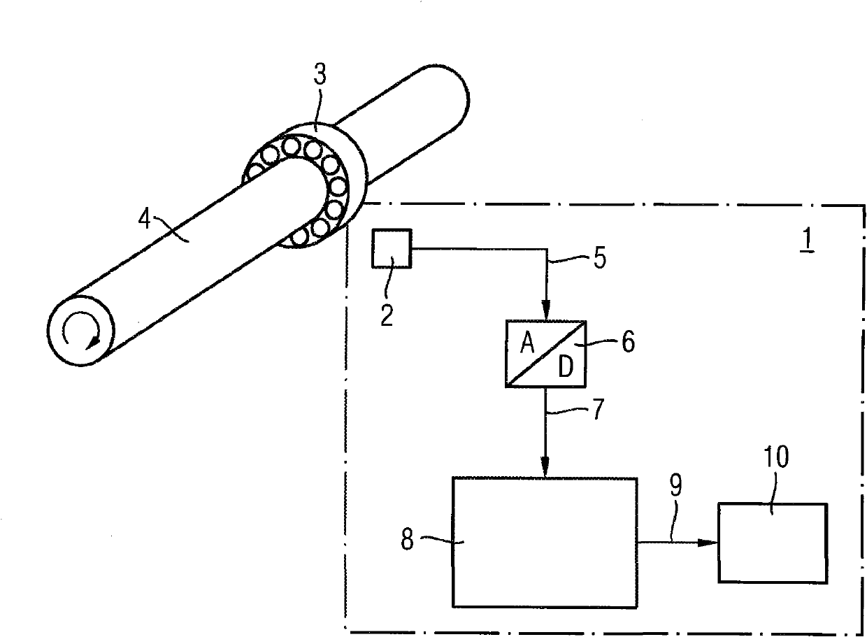
[0034] exist figure 2 In the exemplary embodiment shown, the bearing damage detection device 1 according to the invention has at least one vibration sensor 2 which converts the vibration signals emitted by the bearing 3 into electrical signals. exist figure 2 In the illustrated embodiment, the bearing 3 is a rolling bearing. The rolling bearing 3 serves to support a body 4 that rotates, in particular rotates, at a certain rotational frequency. The rotating object 4 can be as figure 2 The axis of rotation shown. According to a possible embodiment, the vibration sensor 2 can be mounted directly on the bearing 3 in order to detect direct contact vibrations. The vibration sensor 2 can be mounted on the housing of the machine containing the bearing 3 . According to an alternative embodiment, the vibration sensor 2 is arranged at a distance from the bearing 3 for detecting airborne acoustic signals. The vibration sensor 2 may be a microphone, an acceleration sensor, an LVDT...


PUM


Abstract

A device for recognizing bearing damage of a bearing (3), on which an object (4) which rotates at a rotational frequency is mounted, having at least one oscillation sensor (2) for converting an oscillation signal output by the bearing (3) into an electrical signal and having a calculation unit (8) for performing a first frequency transformation for multiple time windows of the oscillation signal to generate multiple time window spectra associated with the particular time windows and for performing a second frequency transformation for multiple frequency bands of the time window spectrograms to generate a multiband modulation spectrum, which, for modulation frequencies which are a function of the rotational frequency of the rotating object (4) because of bearing damage of the bearing (3), have signal amplitudes, the level thereof disclosing an extent of the bearing damage.

Description

technical field [0001] The invention relates to a method and a device for detecting bearing damage, in particular rolling bearing damage. Background technique [0002] Ball bearings or rolling bearings have an inner ring and a movable outer ring separated by a plurality of rolling elements. Rolling friction occurs most frequently between the inner ring, outer ring, and rolling elements (such as balls). Since the rolling elements in the inner and outer rings of conventional rolling bearings slide on hardened steel surfaces with optimized lubrication conditions, the rolling friction of these rolling bearings is relatively low. There are many types of rolling bearings, such as ball bearings or tapered roller bearings. The service life of ball bearings or rolling bearings is related to bearing performance, bearing load and bearing maintenance. Rolling bearings are mainly used to support rotating objects in machines, especially rotating shafts. Rolling bearings can be damaged...

Claims


Application Information

Patent Timeline
Patent Type & Authority Applications(China)
IPC IPC(8): G01N29/14G01N29/44G01N29/46G01M13/04G01H3/08
CPCG01N2291/2696G01M13/045G01N29/46G01N29/4445G01H1/003G01N29/14F16C19/527F16C2233/00
Inventor 约阿西姆·霍费尔卢茨·罗伊泰尔特
Owner SIEMENS AG
Why Eureka
Try Eureka