Flight dropper

A descender and overrunning clutch technology, applied in life-saving equipment, building rescue, etc., can solve problems such as difficulty in rewinding ropes, affecting reuse, affecting safety and lifesaving, and achieves an effect that is conducive to safety and lifesaving

Inactive Publication Date: 2011-04-13
何少敦
View PDF3 Cites 4 Cited by
  • Summary
  • Abstract
  • Description
  • Claims
  • Application Information

AI Technical Summary

Problems solved by technology

[0003] In order to overcome the disadvantages that the known aerial descender is not equipped with a rope rewinding member, there is difficulty in rewinding the rope, affecting repeated use, and affecting safety and lifesaving. The present invention proposes an aerial descender. The principle is: A one-way rotating member is arranged between them. When the rope is lowered, the rope rotates around the disk and drives the crankshaft to rotate. The crankshaft produces no resistance

Method used


Image

  • Flight dropper
  • Flight dropper
  • Flight dropper

Examples


Embodiment Construction

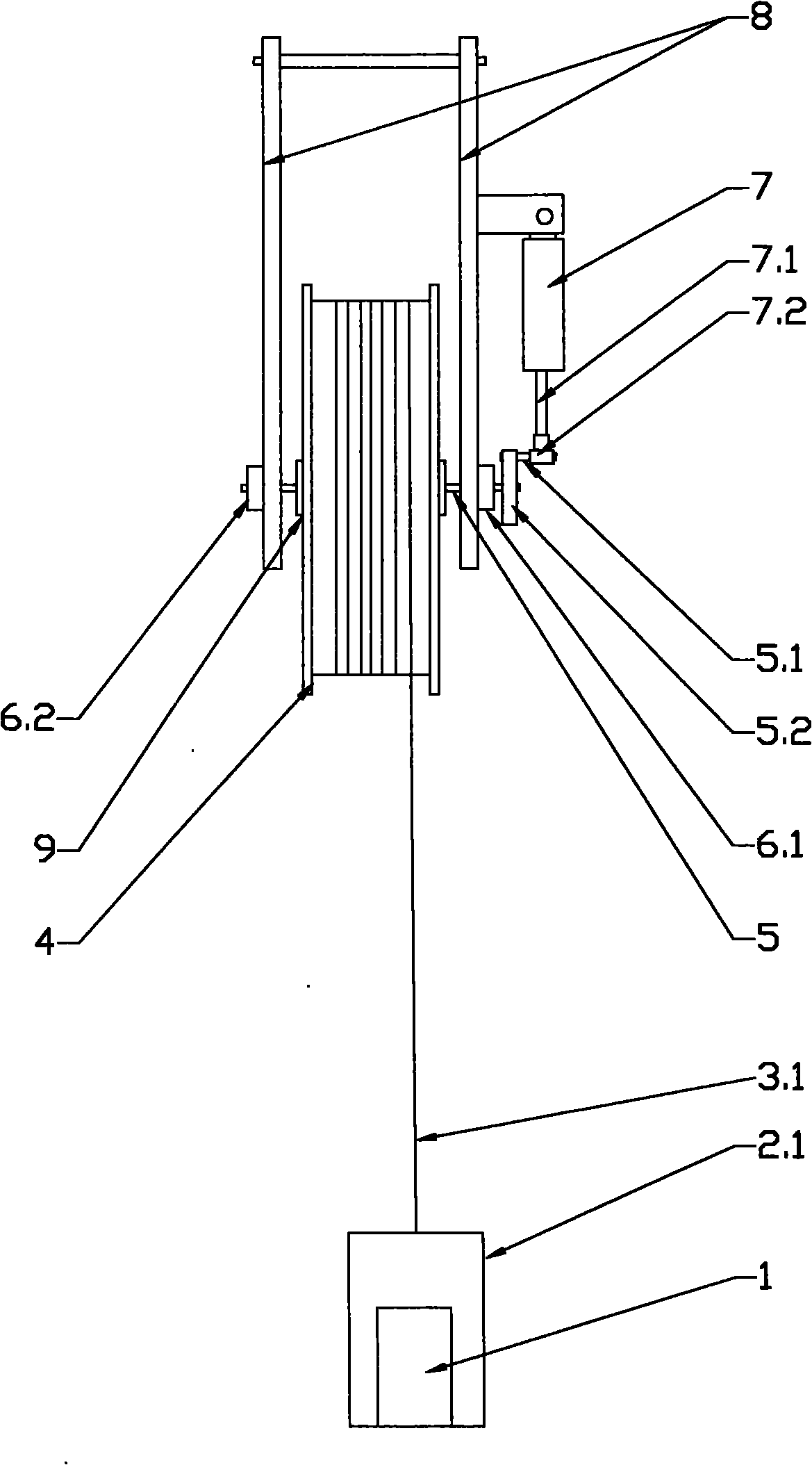
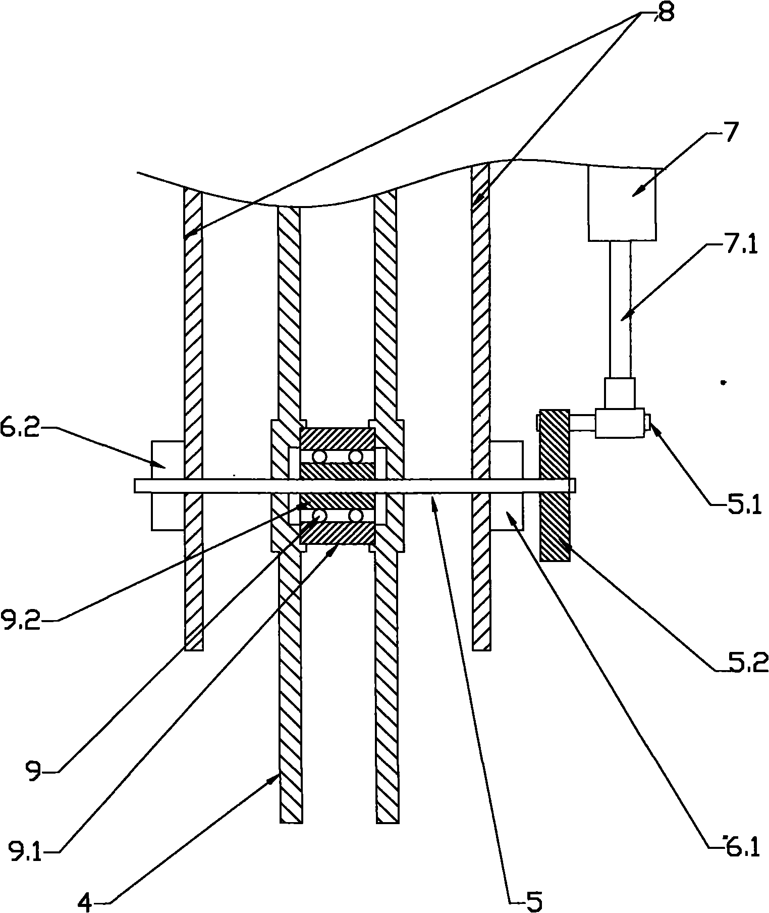
[0018] figure 1 , figure 2 It is a structural schematic diagram of the first embodiment of the present invention; figure 1 is a schematic diagram of the structure, figure 2 It is the schematic diagram of the partially enlarged structure, in figure 1 As shown in , the gravity part 1 is carried by the carrier 2.1, the carrier 2.1 is connected and fixed with the rope 3.1, the rope 3.1 is fixed and wound on the rope coil 4, the rope coil 4 is indirectly installed on the rotating shaft 5, and the rotating shaft 5 passes through Axle bases 6.1 and 6.2 are installed on the support 8, a rotating part 5.2 is installed on the rotating shaft 5, a crankshaft 5.1 is installed on the rotating part 5.2, and the piston rod 7.1 of the piston 7 is connected with the crankshaft 5.1 through the rod end connector 7.2. figure 2 Shown in, the feature of this embodiment is that the rope reel 4 is installed on the rotating shaft 5 through an overrunning clutch 9, the outer ring 9.1 of the overru...


PUM


Abstract

The invention relates to a flight dropper for overcoming the defects that a well-known flight dropper without a rope rewinding member has difficulty in rope rewinding to influence repeated use and safe rescue. The flight dropper provided by the invention has the principle that a one-way rotating member is arranged between a rope winder and a crankshaft; when the rope falls, the rope winder revolves and drives the crankshaft to rotate, and the crankshaft revolves and drives a piston rod to operate; and when the rope is rewound, the rope winder rotates, but the crankshaft does not revolve, and a piston does not generate resistance to the crankshaft since the crankshaft does not revolve. By the one-way rotating member arranged between the rope winder and the crankshaft, a user can conveniently and rapidly rewind the rope, and the invention is rapid and repeated to use and favorable to safe rescue.

Description

technical field [0001] The invention relates to a landing device, in particular to an aerial landing device. Background technique [0002] In daily life or work, people often encounter danger at high places. If there is no other way to escape, they need to escape with the aid of an air landing device. The known air landing devices include friction speed limiting, manual brake speed limiting And hydraulic damping speed-limiting type, the disadvantage of the first two is poor reliability, the last one is relatively simple in structure, and its performance is also relatively reliable. CN87216143 discloses a kind of air landing device that uses piston and cam to play the role of speed-limiting, but the cam only bears pressure and does not Under tension, there is uneven speed limit during the landing process; ZL2003101127389 and ZL2003201232361 respectively disclose a principle of connecting a crankshaft with a hydraulic speed-regulating controller, but due to the use of a chain ...

Claims


Application Information

Patent Timeline
Patent Type & Authority Applications(China)
IPC IPC(8): A62B1/06
CPCA62B1/12
Inventor 何少敦
Owner 何少敦
Why Eureka
Try Eureka