
Locking method using two groups of lock parts and lock core assembly

A lock cylinder and lock technology, which can be used in locks with turning keys, building locks, cylinder marble locks, etc., can solve problems such as unsettled factors in a harmonious society

Inactive Publication Date: 2012-11-28
王晓荡
View PDF0 Cites 0 Cited by
  • Summary
  • Abstract
  • Description
  • Claims
  • Application Information

AI Technical Summary

Problems solved by technology

[0003] The lock cylinder is the core component of the lock. What we usually refer to as the key quantity or mutual opening rate index of the lock depends on the locking structure of the lock cylinder and its locking ability. In order to improve the locking ability of the lock, people have indeed done A lot of work and paid unremitting efforts, but still do not find a way to change to solve the many defects that the existing technology exists, as everyone knows, a key can open the anti-theft door locks of several families in a unit building; An evil technology can be used to steal a car; it can unlock the car lock and steal the car in a few seconds or even a few seconds. It can reflect the existing defects and weaknesses of existing technologies are so prominent: just click on the "unlock" web page, all kinds of lock-picking tools (tools) with all kinds of strange things will appear on the screen, dazzling you, and it despises the lock with a strong posture. Industry, to challenge the lock

Method used


Image

  • Locking method using two groups of lock parts and lock core assembly
  • Locking method using two groups of lock parts and lock core assembly
  • Locking method using two groups of lock parts and lock core assembly

Examples


Embodiment

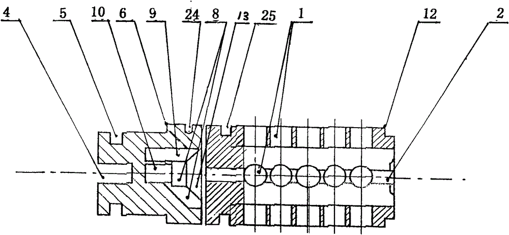
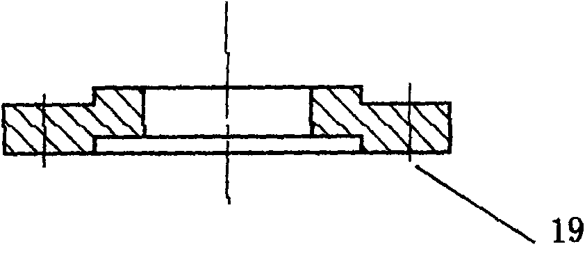
[0067] Embodiment: take ' ten ' type lock core door pong lock as example, Figure 4 Be provided with tail end cover screw hole 19 for the tail end cover of lock core assembly lock head, Figure 5 The code disk is provided with a dial tongue installation groove 4, a dial tongue fixing snap ring 5, a code disk positioning shoulder step 6, a concave code 13 is provided with a code groove 8, a code column 9, a decryption key rotation center positioning hole 10 and a back Bit pin hole 24; Figure 6 The lock cylinder is provided with a locking pin hole 1, a lock cylinder melting groove hole 2, a positioning shoulder step 12 and a positioning ring groove 25; Figure 7 Be provided with outer lock core nut hole 20 for outer lock core (lock sleeve), will Figure 4 Rear end cap shown, Figure 5 The code disk shown, Figure 6 cylinder shown and Figure 7 The shown outer lock core (lock sleeve) cooperates with the assembly, which constitutes as follows: Figure 8 Shown is provided wi...


PUM


Abstract

The invention relates to a locking method using two groups of lock parts and a lock core assembly, wherein the lock core assembly comprises two independent lock parts, namely a lock core and a password disk, a positioning ring groove and a locking marble hole are mounted on the lock core, the lock core further comprises a key tooth containing slot hole, a return marble hole, a password groove anda password column or a password hole are arranged on the password disk, and the end of the password disk is connected with a tongue poking mechanism; correspondingly, two decoding function areas, namely the decoding function area of the password disk and the decoding function area of the lock core are further arranged on a key, and a lock can only be opened by inserting the key into the key toothcontaining slot hole, then leading the key to be in close fit with a marble of the lock core, leading a decryption tooth head of the key to be in close fit with the password groove and the password column or the password hole on the password disk, and rotating the key. When technical unlocking or violent unlocking occurs, even an arranged password of locking the marble is decoded or a locking mechanism of the marble is violently destructed, the lock can not be illegally unlocked, and the anti-theft performance and the security performance of the lock are greatly improved.

Description

technical field [0001] The invention relates to an anti-theft device, in particular to a lock cylinder assembly with two sets of lock parts and a locking method thereof, which is suitable for anti-theft door locks, padlocks, car locks, safe locks, cabinet locks, drawer locks, atomic locks And include all mechanical tumbler locks that are opened by inserting a key into the lock cylinder. Background technique [0002] As early as the early 1950s, the author saw a copper padlock with a body of about 1.8 cm, engraved with a human head and an egg-shaped pattern, and the key of the lock was unilaterally canine-toothed. , that is, today's "pin lock", the "pin lock" structure has been used unchanged for at least sixty years, even if there are some changes, it is just a new trick on the tooth shape and the arrangement of the locking pins, but It is still the same as ever, and it is still the kind of "rectum" type lock cylinder body. [0003] The lock cylinder is the core component ...

Claims


Application Information

Patent Timeline
Patent Type & Authority Patents(China)
IPC IPC(8): E05B63/14E05B27/02E05B35/00E05B19/06
Inventor 王晓荡
Owner 王晓荡
Learn More