Auto-focusing method and module and image pick-up device employing the method
An image capture device and auto-focus technology, applied in the field of image capture, can solve problems such as incomplete images, and achieve cost-saving and easy-to-carry effects
- Summary
- Abstract
- Description
- Claims
- Application Information
AI Technical Summary
Problems solved by technology
Method used
Image


Examples
Embodiment Construction
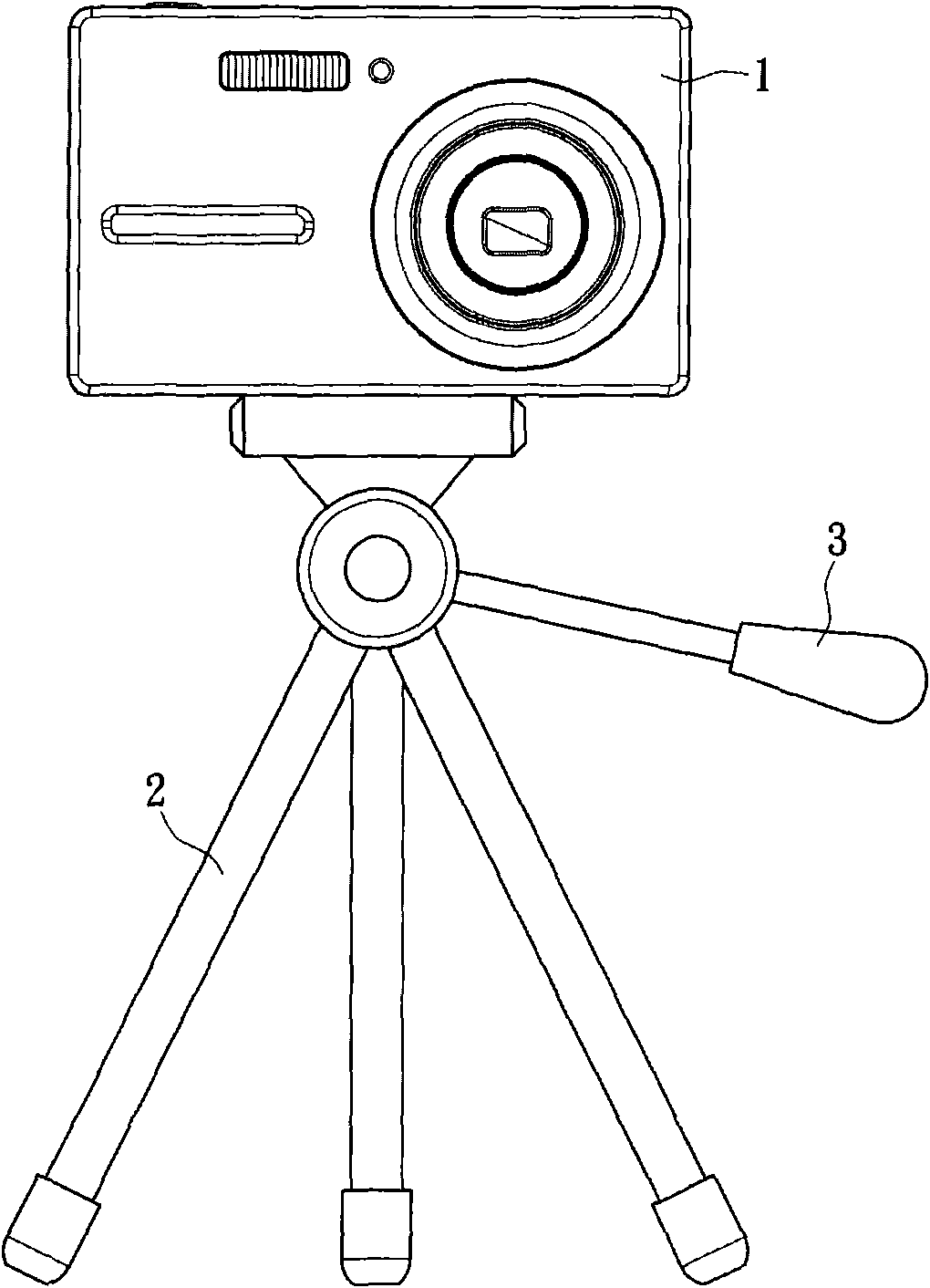
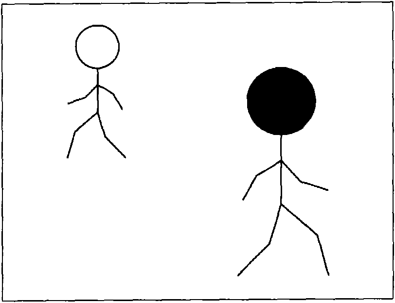
[0049] The present invention relies on the motion detection of the target in the image to keep the target within the viewing range displayed on the display without the need for the user to control the direction of the image capture device in real time.
[0050] In order to provide a more detailed illustration and description, the following will illustrate the present invention with block diagrams and schematic diagrams, so as to more clearly and clearly disclose the technical means used in the present invention, so as to highlight the advantages and capabilities of the present invention. achieved effect.
[0051] The main technical feature of the present invention lies in the image capture device with auto-focus function and its method. Therefore, the following embodiments only propose the necessary system architecture and method steps. However, those of ordinary skill in the art can clearly understand that the following In addition to the components, there are of course other...
PUM
 Abstract
Description
Claims
Application Information