
Cutting method and apparatus

A technology for cutting rings and cups, which is applied in the direction of shearing devices, pipe cutting devices, metal processing equipment, etc., to achieve the effect of quality improvement

Inactive Publication Date: 2011-04-13
CROWN PACKAGING TECH
View PDF1 Cites 2 Cited by
  • Summary
  • Abstract
  • Description
  • Claims
  • Application Information

AI Technical Summary

Problems solved by technology

However, this method can only be used on flat sheet metal blanks to produce cylinders that are open at both ends

Method used


Image

  • Cutting method and apparatus
  • Cutting method and apparatus
  • Cutting method and apparatus

Examples


Embodiment Construction

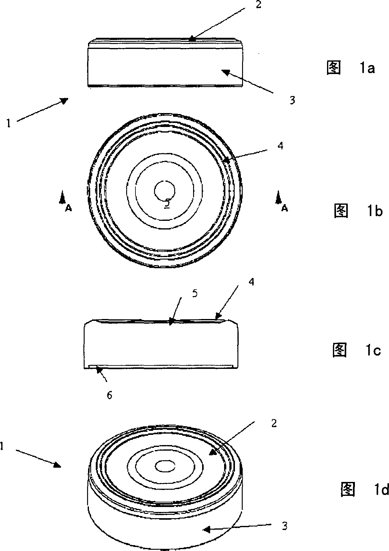
[0059] Figure 1a to Figure 1d A cup 1 is shown comprising an end 2 and an integrally formed side wall 3 . The end 2 is formed into a bead 4 and a center plate 5 during the cup forming process (see Figure 1b and Figure 1c Section through line A-A). The side wall 3 terminates in an inward curl 6 which is best seen in Figure C.

[0060] Figure 2 shows a cut end piece 10 from a single stage process ( Figure 2a ) and cut ring 11 ( Figure 2b ). exist Figure 2c and 2d Their respective cutting edges 12 and 13 are shown in .

[0061] The two-stage option of Figures 3 and 4 first forms a score 15 in the side wall 3 towards the end 2 with a total internal angle 16 of about 60° (degrees) between half and three quarters of the wall thickness. "V" shaped cutout. when Figure 4a When the end piece 2 is divided from the side wall (ring) 3, a flare is formed inwardly through the dividing edges 17 and 18.

[0062] exist Figure 5a and Figure 5b A manual cutting or scoring d...


PUM


Abstract

A method and apparatus for manufacturing a two-part article from a cup (1) formed from a single sheet metal blank. The method includes forming a 'V'-shaped groove (15) by pressing and rolling an anvil (25) on one side of the cup sidewall (3), against one or more cutting rings (21) on the opposite side of the sidewall. Generally, this stage is followed by a second stage, which cuts the cup (1) into a separate ring (11) and shallower cup (10). This second stage enables profiled edges (17, 18) such as slight bends or flares to be formed which are beneficial when flanging or curling of the edges is subsequently required.

Description

technical field [0001] The present invention relates to the cutting of sidewalls of cup-shaped sheet metal cans, closures or the like. In particular, the invention relates to cutting a drawn cup-shaped closure having one or more inwardly projecting features at its rim into separate rings and shallower cup-shaped objects. Background technique [0002] Several methods are known by which cans can be cut (trimmed) to the desired height to produce separate rings. These methods are used in rotary machines such as those commonly supplied by Belvac Production Machinery and Carnaud Metalbox Engineering, and are good where the rings are usually discarded and the height of the cut ring is often significantly less than the height of the trimmed tank suitable for pruning. [0003] WO 08053013A (CROWN PACKAGING TECHNOLOGY, INC.) and unpublished patent application EP-08153134.5 describe a method of manufacturing a two-part closure and the resulting two-part closure, respectively. Produc...

Claims


Application Information

Patent Timeline
Patent Type & Authority Applications(China)
IPC IPC(8): B23D21/14B23D31/00
CPCB23D31/002B23D31/001B23D21/14
Inventor P·R·邓伍迪
Owner CROWN PACKAGING TECH
Learn More