Ultrasonic transducer

A transducer and ultrasonic technology, applied in the direction of the fluid using vibration, can solve the problems of uneven ultrasonic effect, narrow operating frequency bandwidth, weak ultrasonic effect, etc., to avoid energy loss, wide operating frequency bandwidth, and avoid electric shock hazards. Effect

Active Publication Date: 2011-04-20
GUANGDONG GT ULTRASONIC CO LTD
View PDF6 Cites 16 Cited by
  • Summary
  • Abstract
  • Description
  • Claims
  • Application Information

AI Technical Summary

Problems solved by technology

Existing ultrasonic transducers are composed of mass blocks, emitters, piezoelectric elements, etc. The end face of the emitter is a horizontal plane. This kind of transducer needs to be conducted through a stainless steel plate, which is not suitable for human contact, and its operating frequency The bandwidth is narrow, the ultrasonic effect is uneven, and the ultrasonic effect is weak; the piezoelectric element in the existing transducer is composed of at least one piezoelectric chip, which will form a loop when short-circuited, resulting in a risk of electric shock

Method used


Image

  • Ultrasonic transducer
  • Ultrasonic transducer

Examples


Embodiment Construction

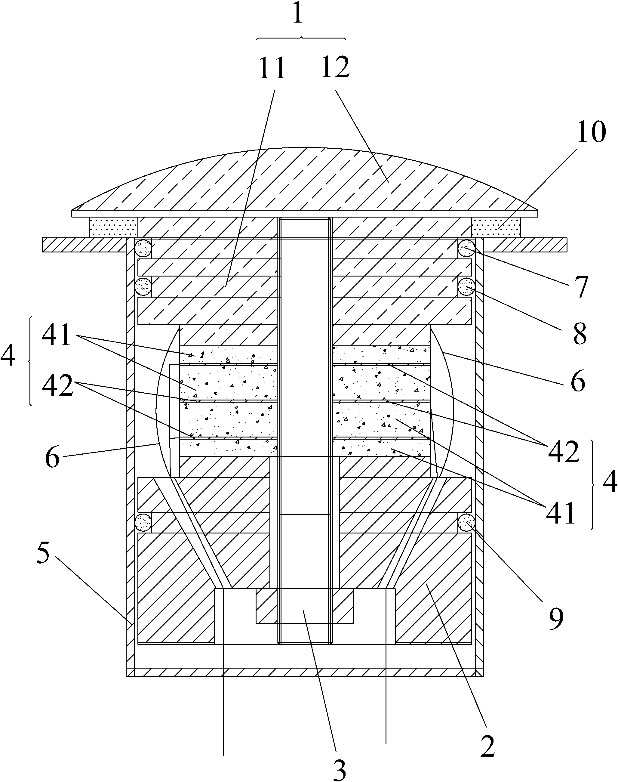
[0008] figure 1 The ultrasonic transducer shown in the present invention includes: a transmitting head 1 , a rear mass block 2 , a bolt 3 , a piezoelectric element 4 and a housing 5 .

[0009] Wherein, the emitter 1 includes a working part 12 whose top surface is a spherical convex surface and a connecting part 11 protruding from the middle part of the bottom surface of the working part 12 and extending into the housing 5, and the connecting part 11 of the emitting head 1 is arranged inside the housing 5 , the working part 12 of the launch head 1 protrudes from the top of the housing 5 . The back-end mass 2 is arranged at the bottom of the housing 5 , and the piezoelectric element 4 is fixed between the emitter head 1 and the back-end mass 2 by bolts 3 , and the bolts 3 are fixed on the connecting portion 11 .

[0010] The piezoelectric element 4 includes at least two piezoelectric ceramic sheets 41 and a non-polar electrode sheet 42 arranged between two adjacent piezoelectri...


PUM


Abstract

The embodiment of the invention relates to an ultrasonic transducer, comprising a shell, an emitter arranged at the top of the shell, a rear-end mass block arranged at the bottom inside the shell and a piezoelectric element fixed between the emitter and the rear-end mass block by a bolt, wherein the emitter comprises a working part with a spherical convex top surface. The ultrasonic transducer has the following beneficial effects: the transducer can be directly contacted with the human body without using a stainless steel plate for conduction, thus avoiding energy loss caused by conduction and giving full play to the ultrasonic power; the transducer has the advantages of wider working frequency bandwidth, concentrated ultrasonic energy and uniform strength; an electrodeless ceramic wafer is arranged between every two piezoelectric ceramic wafers, and loops can not be formed even if short circuit caused by burst of the piezoelectric ceramic wafers happens, thus effectively avoiding the human body from possible electric shock due to contact.

Description

technical field [0001] The invention relates to an ultrasonic device, in particular to an ultrasonic transducer. Background technique [0002] Ultrasonic transducers are key components in ultrasonic cleaners and cleaning equipment that convert piezoelectric effects into mechanical energy vibrations. Existing ultrasonic transducers are composed of mass blocks, emitters, piezoelectric elements, etc. The end face of the emitter is a horizontal plane. This kind of transducer needs to be conducted through a stainless steel plate, which is not suitable for human contact, and its operating frequency The bandwidth is narrow, the ultrasonic effect is uneven, and the ultrasonic effect is weak; the piezoelectric element in the existing transducer is composed of at least one piezoelectric chip, which will form a loop when short-circuited, resulting in the risk of electric shock. Contents of the invention [0003] The technical problem to be solved by the embodiments of the present in...

Claims


Application Information

Patent Timeline
Patent Type & Authority Applications(China)
IPC IPC(8): B06B1/06
Inventor 吴银隆
Owner GUANGDONG GT ULTRASONIC CO LTD
Why Eureka
Try Eureka