Power-saving actuator of direct-current electronic lock

An actuator, electronic lock technology, used in construction locks, non-mechanical transmission-operated locks, construction, etc.

Inactive Publication Date: 2011-04-20
陈悌
View PDF0 Cites 0 Cited by
  • Summary
  • Abstract
  • Description
  • Claims
  • Application Information

AI Technical Summary

Problems solved by technology

[0007] The purpose of the present invention is to overcome the defects existing in the existing electronic lock electric actuator, and provide a new structure of the DC electronic lock power-saving actuator, the technical problem to be solved is to make it have power saving, growth Product life, volume reduction, and noise avoidance

Method used


Image

  • Power-saving actuator of direct-current electronic lock
  • Power-saving actuator of direct-current electronic lock
  • Power-saving actuator of direct-current electronic lock

Examples


Embodiment Construction

[0049] In order to further explain the technical means and effects of the present invention to achieve the intended purpose of the invention, the specific implementation and structure of the power-saving actuator for the DC electronic lock proposed according to the present invention will be described below in conjunction with the accompanying drawings and preferred embodiments. , features and their functions are described in detail.

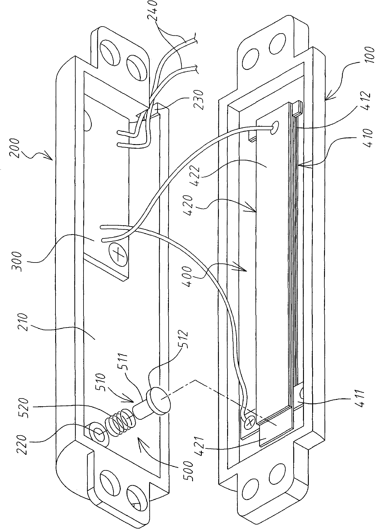
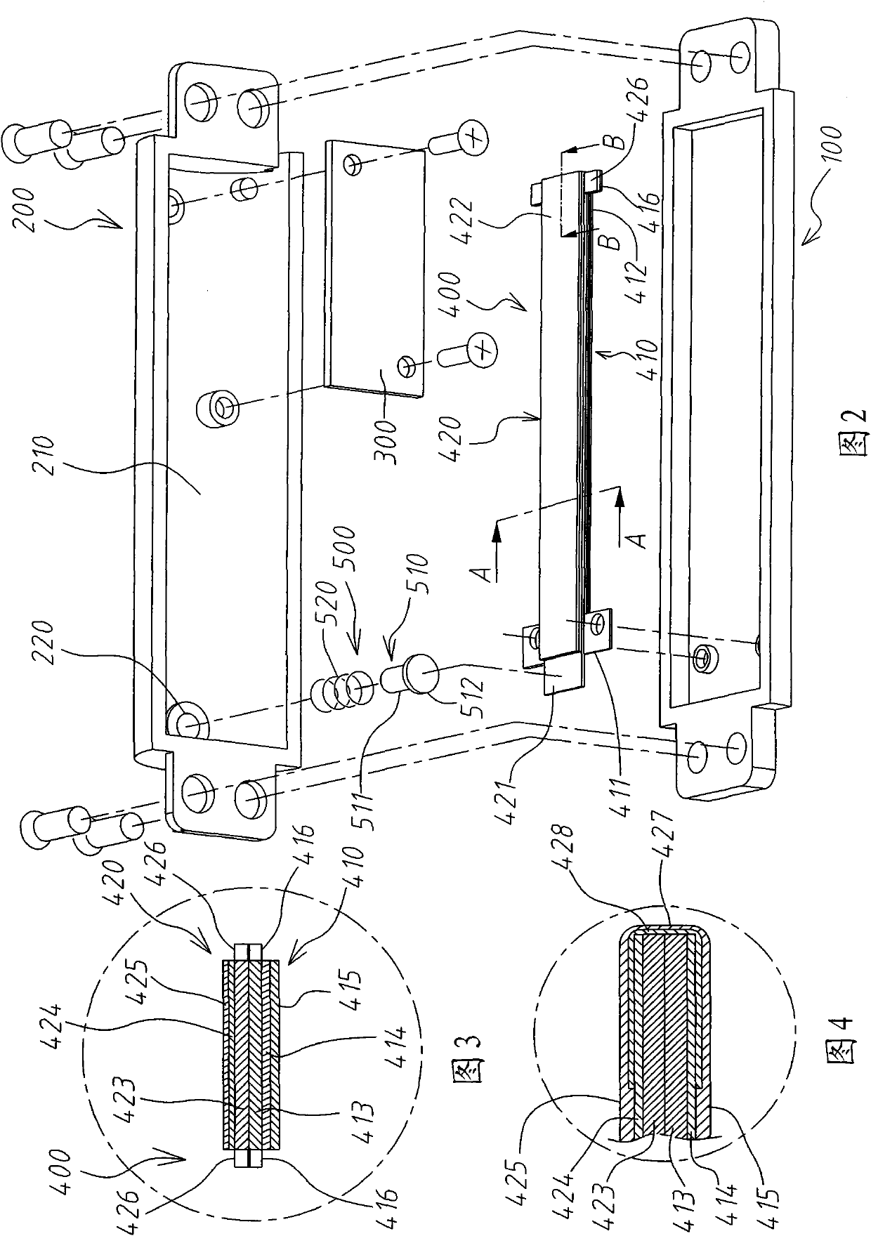
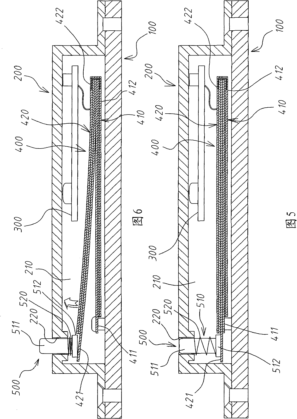
[0050] see Figure 1 to Figure 5 Shown are an exploded view and a cross-sectional view of the power-saving actuator of the DC electronic lock according to an embodiment of the present invention, respectively. As shown in these drawings, the power-saving actuator of the DC electronic lock in the preferred embodiment of the present invention includes a first housing 100, a second housing 200, a circuit board 300, and a piezoelectric ceramic steel sheet Assembly 400, and a male tip unit 500.

[0051] The first shell 100 and the second shell 200 ar...


PUM


Abstract

The invention relates to a power-saving actuator of a direct-current electronic lock, comprising a first shell, a second shell, a piezoelectric ceramic steel disc assembly, a circuit board and a convex tip unit, wherein the first shell and the second shell are combined and fixed mutually, and the top of the second shell is provided with a through hole; the piezoelectric ceramic steel disc assembly is formed by laminating a first piezoelectric ceramic steel disc and a second piezoelectric ceramic steel disc, wherein the first end of the second piezoelectric ceramic steel disc is a free end; the circuit board is electrically connected to the piezoelectric ceramic steel disc assembly; and the convex tip unit comprises a convex tip and a spring which are sleeved with each other, and the convex tip unit is positioned between the top of the first end of the second piezoelectric ceramic steel disc and a through hole. The circuit board applies a voltage to the piezoelectric ceramic assembly so that the first end of the second piezoelectric ceramic steel disc generates upwards inflected displacement changes and pushes the convex tip of the convex tip unit to outwards extend from the through hole, thereby a lock bolt is interfered and actuated.

Description

technical field [0001] The invention relates to an actuator, in particular to a power-saving actuator for a direct current (DC) electronic lock. Background technique [0002] The electronic lock is to control the extension or retraction of the deadbolt in an electric way, so as to achieve the function of locking or unlocking. [0003] There are generally two types of actuators for electronic locks according to their actuation methods. One is a motor-driven type, which drives the lock tongue through the gear through the rotation of the motor rotor to achieve the actuation effect; the other is a solenoid structure (so1enoid), also known as a solenoid valve, which uses an electromagnetic coil to generate magnetic force to control a protruding shaft. Drive the lock tongue to achieve the actuation effect. [0004] However, these existing known actuators all use the principle of coils to generate sufficient magnetic force, so they must be driven with a relatively large current a...

Claims


Application Information

Patent Timeline
IPC IPC(8): E05B47/00E05B15/14
Inventor 陈悌
Owner 陈悌
Why Eureka
Try Eureka