Imaging lens system

An imaging lens, lens technology, applied in optics, instruments, optical components, etc., can solve the problem of the total length of the lens, etc., and achieve the effects of improving sensitivity, reducing sensitivity, and correcting aberrations

Active Publication Date: 2011-04-20
LARGAN PRECISION
View PDF1 Cites 40 Cited by
  • Summary
  • Abstract
  • Description
  • Claims
  • Application Information

AI Technical Summary

Problems solved by technology

[0004] In order to solve the problem that the existing imaging lens system cannot meet higher-order photographic lenses and is applied to high-pixel mobile phones, the total length of the lens is too long, the present invention provides an imaging lens system, which sequentially includes from the object side to the image side: A first lens with positive refractive power, the object-side surface is convex; a second lens with negative refractive power; a third lens with positive refractive power, at least one of the object-side surface and the image-side surface is Aspheric surface; a fourth lens, whose image side surface is aspherical, and the image side surface of the fourth lens is provided with at least one inflection point; a fifth lens, whose object side surface is concave, and the fifth lens At least one of the object-side surface and the image-side surface is an aspherical surface; and a diaphragm is arranged between the subject and the second lens

Method used


Image

  • Imaging lens system
  • Imaging lens system
  • Imaging lens system

Examples


no. 1 example

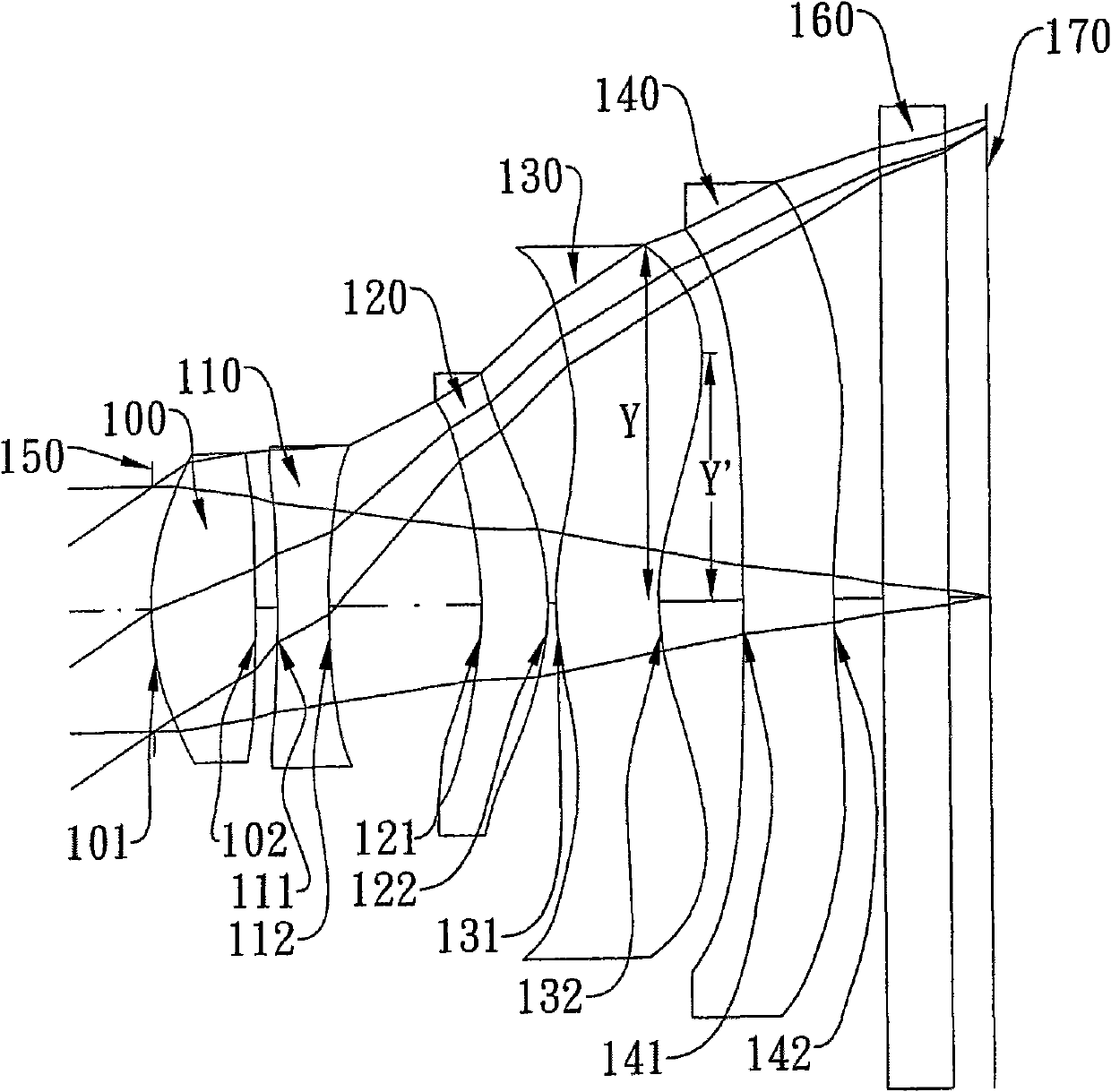
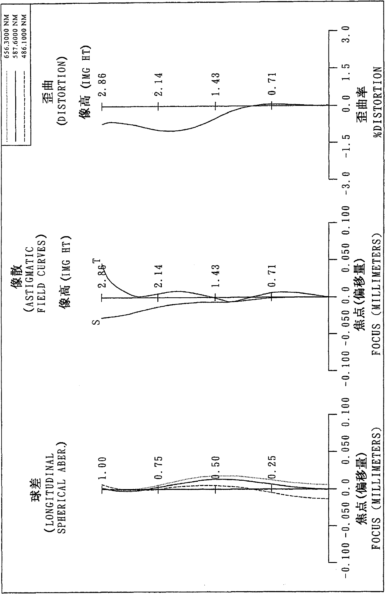
[0084] Please refer to the first embodiment of the present invention figure 1 , for the aberration curve of the first embodiment, please refer to figure 2 . The imaging lens system of the first embodiment is mainly composed of five lenses, which sequentially include from the object side to the image side:

[0085] A first lens (100) with positive refractive power, its object-side surface (101) and image-side surface (102) are both convex, and its material is plastic, the object-side surface (101) of the first lens (100) , The image side surface (102) is all aspherical;

[0086] A second lens (110) with negative refractive power, its object-side surface (111) and image-side surface (112) are all concave, and its material is plastic, the object-side surface (111) of the second lens (110) , The image side surface (112) is all aspherical;

[0087] A third lens (120) with positive refractive power, its object side surface (121) is concave and image side surface (122) is convex...

no. 3 example

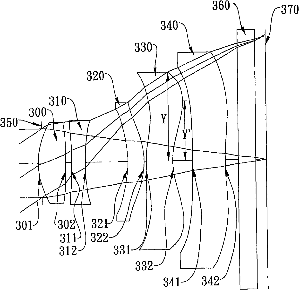
[0155] Please refer to the third embodiment of the present invention Figure 5 , for the aberration curve of the third embodiment, please refer to Image 6 . The imaging lens system of the third embodiment is mainly composed of five lenses, which sequentially include from the object side to the image side:

[0156] A first lens (500) with positive refractive power, its object-side surface (501) and image-side surface (502) are both convex, and its material is plastic, the object-side surface (501) of the first lens (500) , The image side surfaces (502) are all aspheric surfaces;

[0157] A second lens (510) with negative refractive power, its object-side surface (511) and image-side surface (512) are both concave, and its material is plastic, and the object-side surface (511) of the second lens (510) , The image side surfaces (512) are all aspheric surfaces;

[0158] A third lens (520) with positive refractive power, its object side surface (521) is a concave surface and t...

no. 4 example

[0188] Please refer to the fourth embodiment of the present invention Figure 7 , for the aberration curve of the fourth embodiment, please refer to Figure 8 . The imaging lens system of the fourth embodiment is mainly composed of five lenses, which sequentially include from the object side to the image side:

[0189] A first lens (700) with positive refractive power, its object-side surface (701) and image-side surface (702) are both convex, and its material is plastic, and the object-side surface (701) of the first lens (700) , The image side surfaces (702) are all aspheric surfaces;

[0190] A second lens (710) with negative refractive power, its object side surface (711) and image side surface (712) are all concave, and its material is plastic, the object side surface (711) of the second lens (710) , The image side surface (712) is all aspherical;

[0191] A third lens (720) with positive refractive power, its object side surface (721) is a concave surface and the ima...


PUM

PropertyMeasurementUnit
dispersion coefficientaaaaaaaaaa

Abstract

The invention discloses an imaging lens system. The imaging lens system comprises a first lens, a second lens, a third lens, a fourth lens, a fifth lens and an aperture sequentially from an object side to an image side, wherein the first lens is provided with a positive flexion force; the surface of the object side of the first lens is a convex surface; the second lens is provided with a negative flexion force; the third lens is provided with a positive flexion force; at least one surface of the object side and the image side of the third lens is an aspheric surface; the surface of the image side of the fourth lens is an aspheric surface; the surface of the image side of the fourth lens is provided with at least one inflexion point; the surface of the object side of the fifth lens is a concave surface; at least one surface of the object side and the image side of the fifth lens is an aspheric surface; and the aperture is arranged between a shot object and the second lens. According to the configuration mode, the total optical length of the imaging lens system can be effectively shortened, the sensitivity of an optical system can be reduced and the imaging property of the system can be improved.

Description

technical field [0001] The invention relates to an imaging lens system, in particular to a miniaturized imaging lens system applied to a mobile phone camera. Background technique [0002] In recent years, with the rise of mobile phone cameras, the demand for miniaturized photographic lenses has increased day by day, and the photosensitive components of general photographic lenses are nothing more than photocoupled devices (Charge Coupled Device, CCD) or complementary metal oxide semiconductors (Complementary Metal-Oxide Semiconductor) , CMOS) two types, and due to the progress of semiconductor manufacturing process technology, the pixel area of ​​the photosensitive component is reduced, and the miniaturized photographic lens is gradually developing into the high-pixel field. Therefore, the requirements for imaging quality are also increasing. [0003] Traditional miniaturized photographic lenses mounted on mobile phone cameras, as shown in U.S. Patent No. 7,365,920, mostly a...

Claims


Application Information

Patent Timeline
Patent Type & Authority Applications(China)
IPC IPC(8): G02B13/00G02B13/18G02B1/04
Inventor 汤相岐陈俊杉林铭清
Owner LARGAN PRECISION
Why Eureka
Try Eureka