Multi-layer cavity device with liftable shielding plates

A technology for lifting baffles and cavities, which is applied in the manufacturing of semiconductor/solid-state devices, electrical components, circuits, etc., can solve the problem of turbulent flow in the wafer, and achieve the effects of rapid response, low price and convenient installation.

Active Publication Date: 2012-04-11
SHENYANG KINGSEMI CO LTD
View PDF0 Cites 0 Cited by
  • Summary
  • Abstract
  • Description
  • Claims
  • Application Information

AI Technical Summary

Problems solved by technology

[0003] In order to overcome the above-mentioned deficiencies, the purpose of the present invention is to provide a multi-layer chamber device with liftable baffles, which solves the problems of turbulent flow above the wafer in the prior art.

Method used


Image

  • Multi-layer cavity device with liftable shielding plates
  • Multi-layer cavity device with liftable shielding plates
  • Multi-layer cavity device with liftable shielding plates

Examples


Embodiment Construction

[0017] The present invention will be described in detail below in conjunction with the accompanying drawings.

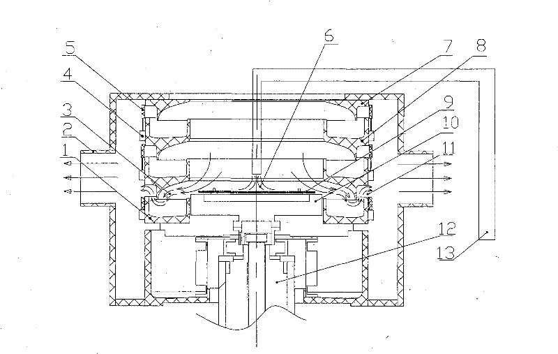
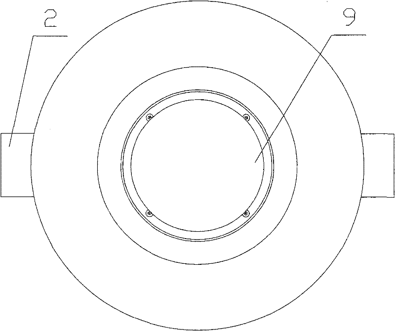
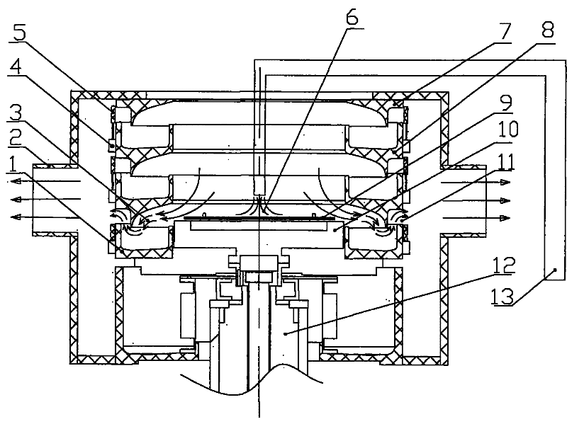
[0018] Such as Figure 1-2 As shown, the multi-layer cavity device with liftable baffles of the present invention mainly includes: the bottom layer of the cavity 1, the exhaust pipe 2, the air flow direction 3, the telescopic cylinder 4, the annular windshield 5, the chemical liquid 6, the cavity The upper layer 7, the middle layer of the cavity 8, the wafer 9, the wafer holder 10, the air outlet 11, the motor 12, the chemical liquid arm 13, etc., the specific structure is as follows:

[0019] The cavity upper layer 7, the cavity middle layer 8, and the cavity bottom layer 1 are arranged up and down to form a multilayer cavity with a stacked structure. The cavity middle layer 8 can be at least one layer, and the number of layers can be freely increased or decreased according to the process requirements. An annular windshield 5 and a telescopic cylinder 4 are arrange...


PUM


Abstract

The invention relates to a multi-layer cavity device with liftable wind shielding plates, which belongs to the field of wafer wet processing in the semiconductor industry and is used for better controlling and processing the airflow form in the cavity of the wafer. The multi-layer cavity device is provided with a plurality of annular wind shield sheets, a telescopic cylinder, a plurality of layers of cavities and the like. The cavities are layered and can be freely increased and decreased in layer number according to the need of the process. The air outlet of the cavity in each layer is provided with one annular wind shielding plate and is opened and closed freely under the movement of the telescopic cylinder. When the wafer is in a certain working position, the air outlet of the cavity in the layer is opened, and the air outlets of the cavities in other layers are closed so that the airflow integrally flows out of the air outlet of the cavity in the layer, the generation frequency ofturbulent airflow can be reduced, and the splashing of chemical liquids can be effectively prevented so as not to pollute the wafer. Because the air outlets of the multi-layer cavities used for wet processing are additionally provided with the annular wind shielding plates, the air can be effectively prevented from flowing in and out of the cavities in all layers, and the airflow can be adjusted to be more stable and smooth in the cavities.

Description

technical field [0001] The invention relates to the field of wafer wet processing in the semiconductor industry, in particular to a multilayer cavity device with a liftable baffle. Background technique [0002] At present, the wafer table needs to be raised and lowered during the wet processing of the multi-layer chamber. When the wafer table is at a low position, the exhaust air mainly removes the gas in the upper part of the chamber, and has little effect on the air flow above the lower wafer. At this time Turbulent flow tends to form above the wafer, which may cause backsplash of droplets and contaminate the wafer. Contents of the invention [0003] In order to overcome the above-mentioned shortcomings, the object of the present invention is to provide a multi-layer chamber device with liftable baffles, which solves the problems of turbulent flow above the wafer in the prior art. [0004] Technical scheme of the present invention is: [0005] The utility model relates...

Claims


Application Information

Patent Timeline
Patent Type & Authority Patents(China)
IPC IPC(8): H01L21/02
Inventor 谷德君
Owner SHENYANG KINGSEMI CO LTD
Why Eureka
Try Eureka