
Paying-off system and method

A technology for pay-off pulleys and wires, applied in the directions of overhead lines/cable equipment, cable railways, motor vehicles, etc., can solve the problems of insufficiency, waste of resources, stretching equipment, and too many traction rope wires, etc., so as to improve the lack of traction, Improve the effect of waste of resources

Active Publication Date: 2011-04-20
STATE GRID CORP OF CHINA +2
View PDF0 Cites 7 Cited by
  • Summary
  • Abstract
  • Description
  • Claims
  • Application Information

AI Technical Summary

Problems solved by technology

However, the "one pull 6" method requires about 40 tons of traction force, which cannot be met by the tractor with the largest tonnage in China (maximum continuous traction force of 25 tons).
"One traction 2 + one traction 4" mode, the traction force of "one traction 4" reaches 27 tons, which is still not enough for the tractor with the largest tonnage in China
However, the "3×one pull 2" method uses too many stretching equipment, traction ropes, and wires, resulting in waste of resources

Method used

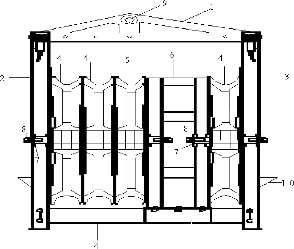
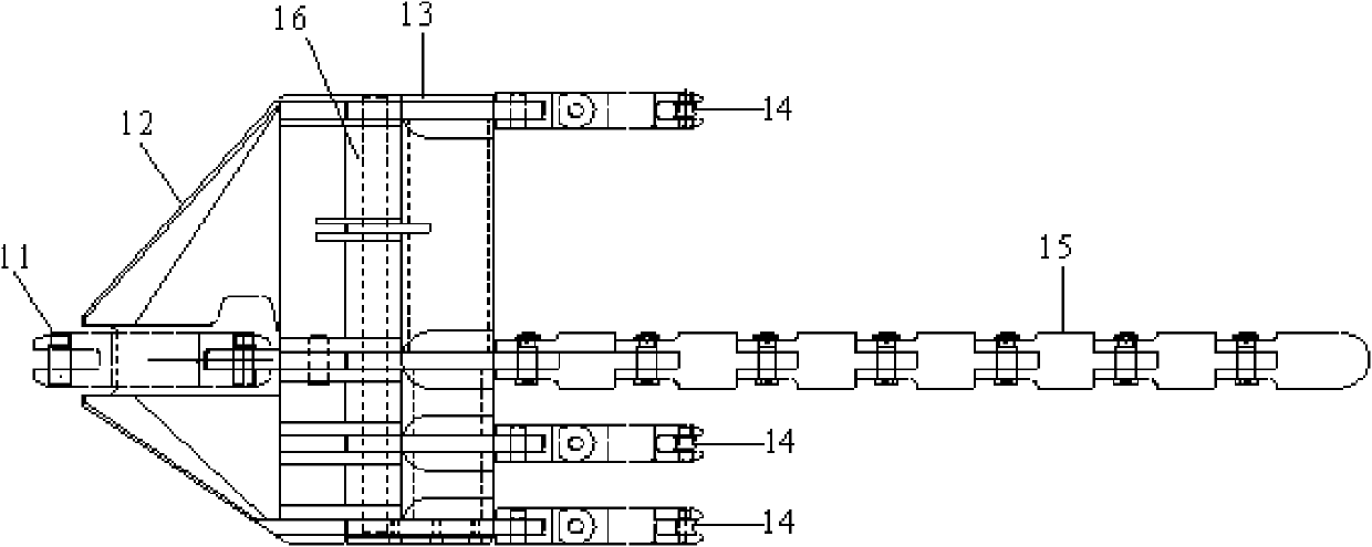

Image

  • Paying-off system and method
  • Paying-off system and method
  • Paying-off system and method

Examples


Embodiment Construction

[0022] The purpose, functions and advantages of the present invention will be further described with reference to the accompanying drawings in conjunction with the embodiments.

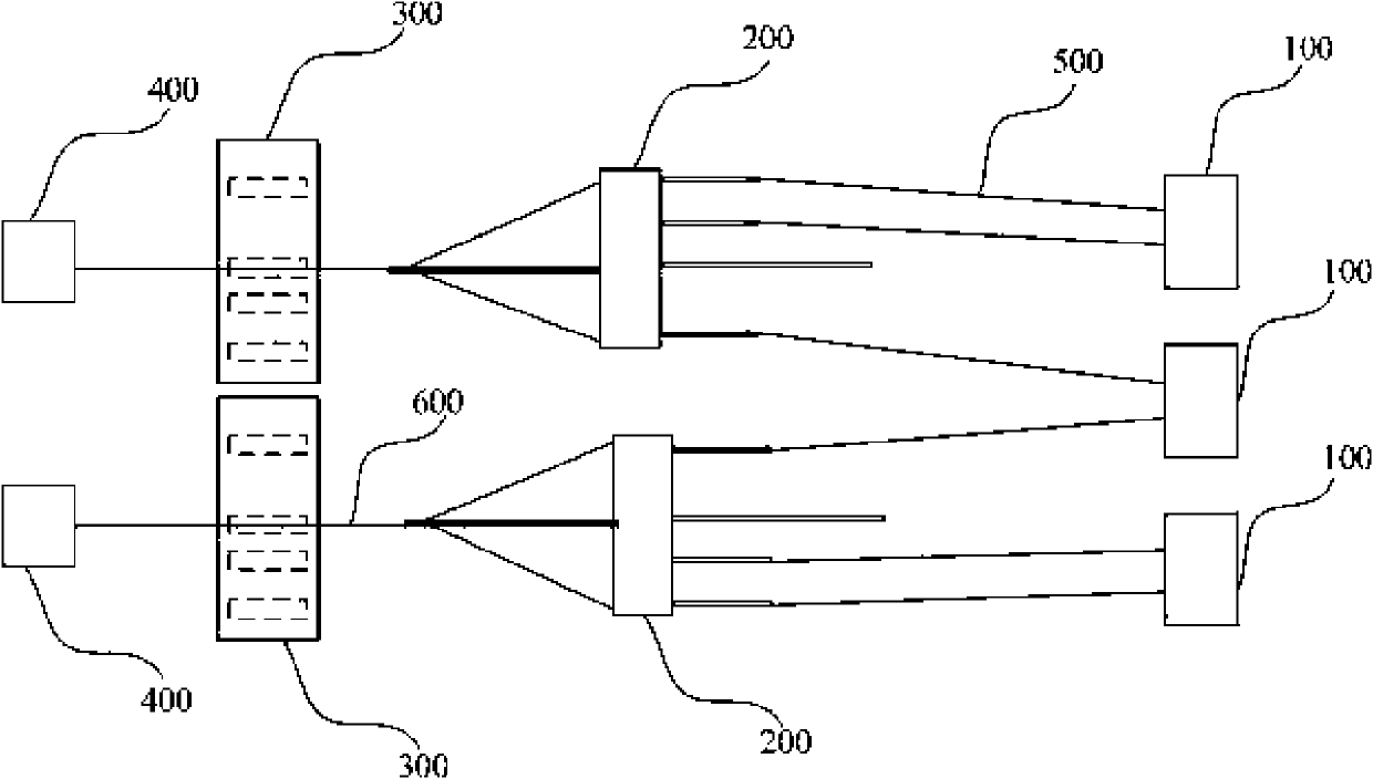
[0023] The pay-off system provided by the embodiment of the present invention may include at least one tractor as the main traction device, at least two tension machines and at least one pay-off tackle. The traction machine pulls the three conductors laid out by the two tension machines through a traction rope laid out by it through the three lead pulleys of the pay-off block. Such as figure 1 As shown, a pay-off system of 2×"one pull 3" can be formed. The 2×"one pull 3" pay-off system may include two tractors 400, two pay-off tackles 300 and three tension machines 100.

[0024] During setting-out construction, two tractors 400 (such as 25 tons) are set as the main traction equipment in the traction field, three second-line tension machines 100 are set in the Zhang stand, and two sets of mutually in...


PUM


Abstract

The invention discloses a paying-off system, comprising at least one dragger used as main dragging equipment, at least two tension machines and at least one paying-off tackle, wherein the dragger is used for dragging three leads released by the two tension machines to pass three lead glide wheels of the paying-off tackle through a dragging rope released by the dragger. The invention also discloses a paying-off method. The method comprises the following steps: at least one dragger is arranged in a dragging field and used as the main dragging equipment; at least two tension machines are arranged in a tension field; at least one paying-off tackle is hung at each phase of an iron tower; the dragging rope is released by the dragger, and at least three leads are released by the two tension machines; and the three leads are dragged by the dragging rope passing a dragging glide wheel of the paying-off tackle to pass the three lead glide wheels of the paying-off tackle. Through the paying-off system and the method of the invention, the problem that the dragger has insufficient drag force and the problem of wasting resources caused by too much investment in the dragging equipment and the dragging rope can be improved when applied to a large-section leads.

Description

technical field [0001] The invention belongs to the field of stringing construction, and in particular relates to a wire-laying system and method suitable for ultra-high voltage power grid construction. Background technique [0002] In the construction of UHV power grids, large cross-sections (such as 900mm 2 , 1000mm 2 cross-section) wires for setting-out construction, but there are problems such as the use of stretching equipment, too many traction ropes and wires, and insufficient traction in the current setting-out construction process. For example: Jin-Su ±800kV DC UHV line adopts 6×900mm 2 Large section wire, this is 900mm 2 For the first application of cross-section conductors in domestic transmission lines, the method of laying out wires has become the primary problem faced by construction units. At present, the industry can provide other pay-off methods as follows: ① "one pull 6" method: 6 wires are driven by one traction rope for traction; ② "3×one pull 2" meth...

Claims


Application Information

Patent Timeline
IPC IPC(8): H02G1/02B61B7/06
Inventor 陈茂生计建军刘钧郎福堂陈其泽梅丰侯先智张明辉
Owner STATE GRID CORP OF CHINA
Learn More