
Device and method for pumping a cryogenic fluid

A low-temperature fluid, low-temperature liquid technology, applied in pump devices, fluid parameters, pumps, etc., can solve problems such as slowness, reduction of supercooled water, etc.

Active Publication Date: 2011-04-20
LAIR LIQUIDE SA POUR LETUDE & LEXPLOITATION DES PROCEDES GEORGES CLAUDE
View PDF9 Cites 7 Cited by
  • Summary
  • Abstract
  • Description
  • Claims
  • Application Information

AI Technical Summary

Problems solved by technology

[0011] During operation of these known systems, ambient temperature hydrogen injected into the top of the vessel slowly heats the liquid, reducing the available level of subcooling

Method used


Image

  • Device and method for pumping a cryogenic fluid
  • Device and method for pumping a cryogenic fluid
  • Device and method for pumping a cryogenic fluid

Examples


Embodiment Construction

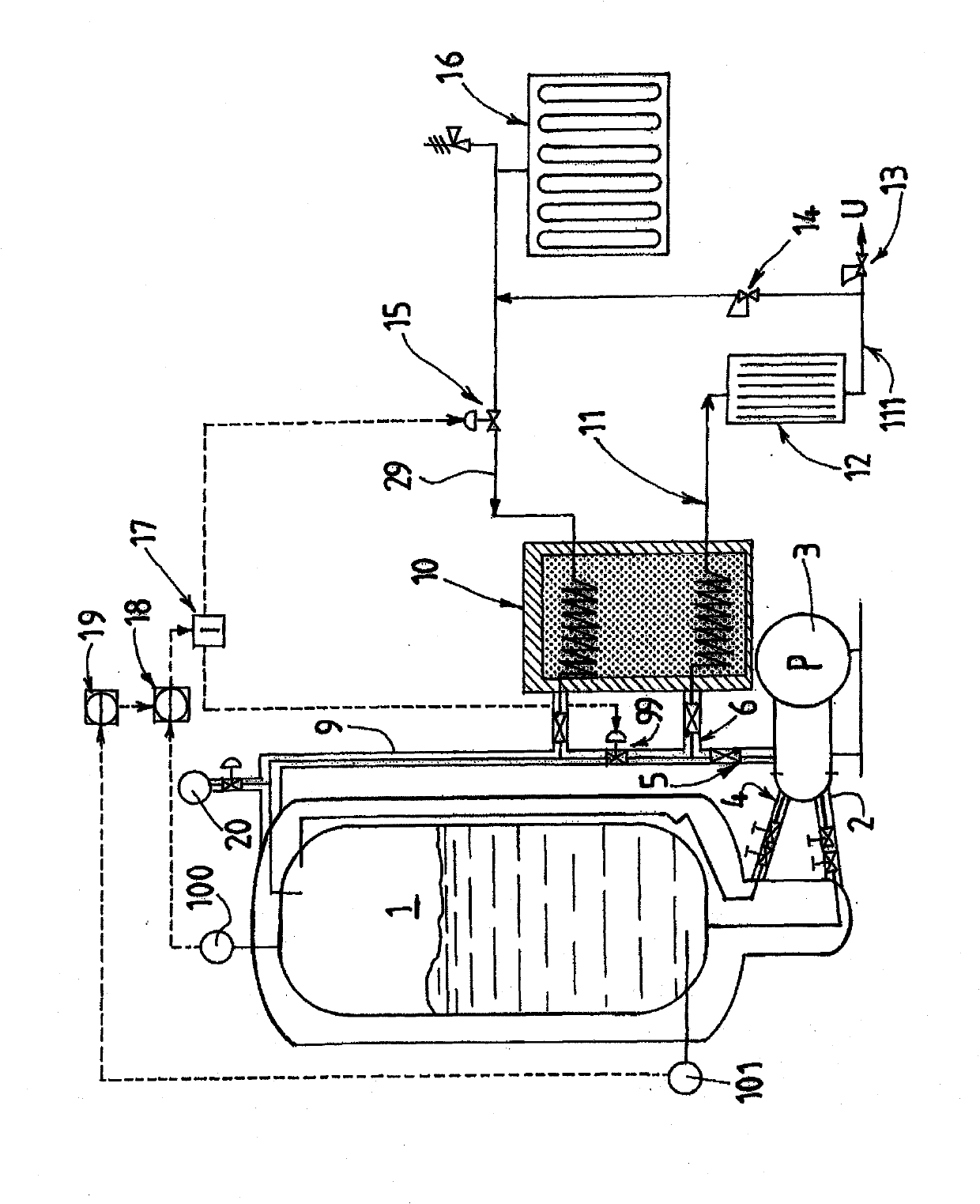
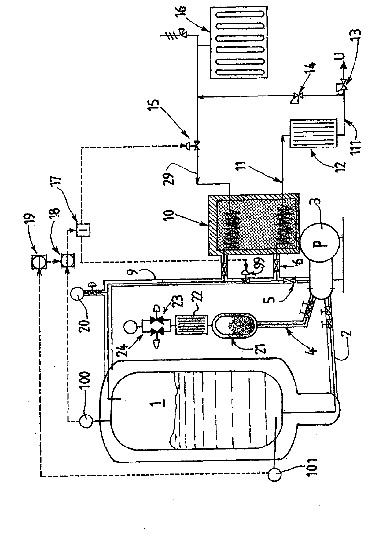
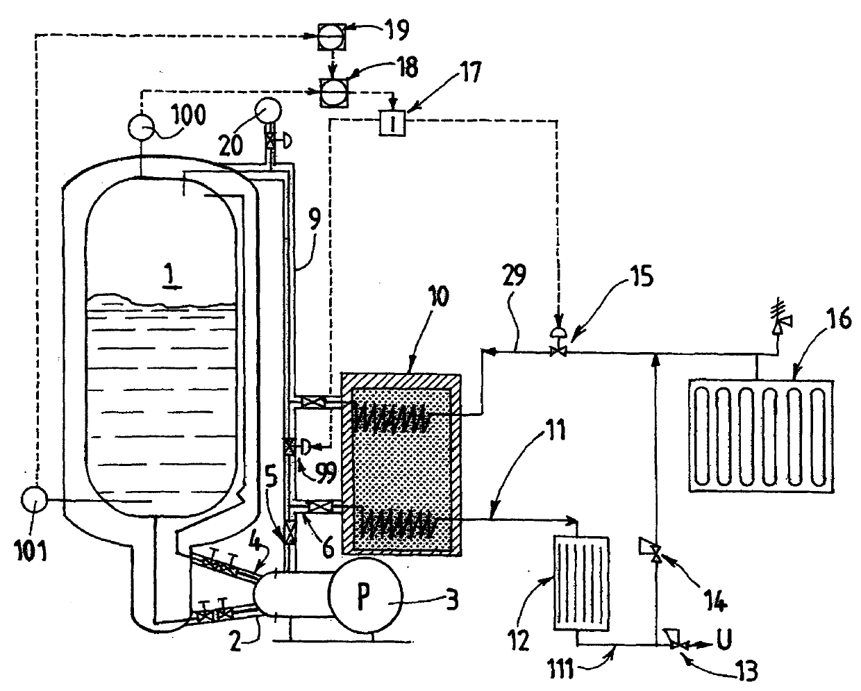
[0040] now refer to figure 1 , the device comprises a container 1 (vacuum isolated) of a cryogenic fluid comprising, for example, a liquid-gas mixture at a certain temperature and an absolute pressure between 1 bar and 12 bar. The temperature and the pressure in the container 1 are measured by means of corresponding sensors 101 , 100 .

[0041] The lower part of the container 1 is connected to the suction inlet of the cryopump 3 through a suction line 2 which is vacuum isolated and has one or more isolation valves.

[0042] The pump 3 comprises a gas discharge line 4 (for gas generated eg by heating / friction) which discharges the gas to the upper part of the container 1 and is fitted with a valve.

[0043] The pump is connected to a high pressure delivery line 5 usually incorporating a delivery valve (high pressure outlet for the fluid being pumped). The high-pressure delivery line 5 is connected to a cold hydrogen supply line 6, which supplies cold hydrogen to an exchanger 10...


PUM


Abstract

The invention relates to a device for pumping a cryogenic fluid, consisting of a tank (1) for storing a cryogenic fluid containing cryogenic liquid, a cryogenic pump (3) having an inlet pressure loss (net positive suction head, NPSH), and a suction line (2) connecting the tank (1) to the pump (3), said pumping device including a system (9, 18, 19) for controlling the pressure in the tank (1) for selectively maintaining said pressure at least equal to the saturation pressure of the stored cryogenic fluid plus the inlet pressure loss (NPSH) of the cryogenic pump and optionally plus the value of the pressure losses owing to the pipes forming the suction line (2) connecting the tank (1) to the pump (3). The invention is characterised in that the pressure-control system (9, 18, 19) includes a duct (9) connecting a high-pressure outlet of the pump (3) to the tank (1) for selectively returning the pumped cold fluid to the tank (1), said duct (9) including an expansion valve (99) for returning cold gas to the tank (1).

Description

technical field [0001] The present invention relates to an apparatus and method for pumping cryogenic fluids. [0002] In particular, the present invention relates to an apparatus for pumping a cryogenic fluid, the apparatus comprising: a storage container for storing a cryogenic fluid including a cryogenic liquid; a cryogenic pump having inlet head loss (NPSH); A suction line connected to a pump, said pumping means comprising a system for controlling the pressure within the vessel for selectively maintaining the pressure within the vessel at least equal to the sum of: The saturation pressure is added to the inlet head loss (NPSH) of the cryopump and optionally also the head loss value due to the piping of the suction line connecting the vessel to the pump. Background technique [0003] The invention is particularly advantageously applied in the field of pumping low-density cryogenic fluids comprising gases such as hydrogen or helium and their isotopes. [0004] Compressin...

Claims


Application Information

Patent Timeline
Patent Type & Authority Applications(China)
IPC IPC(8): F04B15/08F04B23/02
CPCF04B15/08Y02E60/321F04B2205/01F04B23/02
Inventor L·阿利迪热斯
Owner LAIR LIQUIDE SA POUR LETUDE & LEXPLOITATION DES PROCEDES GEORGES CLAUDE
Learn More