

Body composition measuring device
A body composition, measuring device technology, used in diagnostic recording/measurement, medical science, sensors, etc.
- Summary
- Abstract
- Description
- Claims
- Application Information
AI Technical Summary
Problems solved by technology
Method used
Image


Examples
no. 1 Embodiment approach
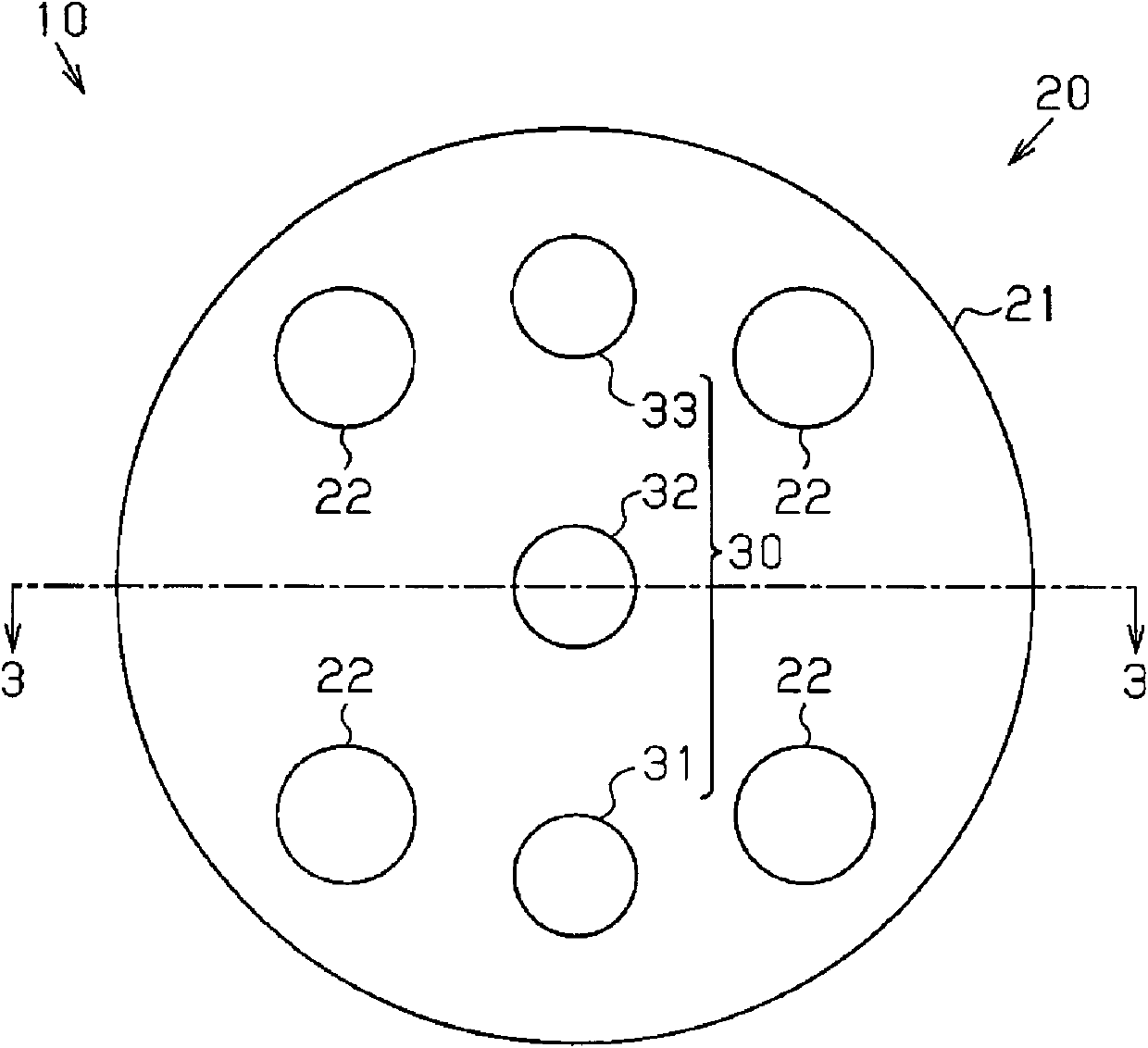
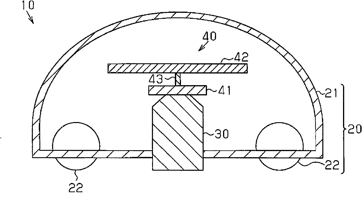
[0031] refer to figure 1 , the structure of the subcutaneous fat measurement device 10 as the body composition measurement device of the first embodiment will be described.
[0032] like figure 1 As shown, the subcutaneous fat measurement device 10 includes: a measurement unit 20 that irradiates light to the body surface 4 and receives light that propagates into the living body 1;
[0033] The measuring unit 20 includes: a unit main body 21; an optical measuring part 30, which is arranged on the unit main body 21; a pressing force measuring part 40, which is used to measure the pressing force of the optical measuring part 30 on the body surface 4; a sphere 22, This allows the measurement unit 20 to move smoothly on the body surface 4 . In the illustrated example, the optical measuring unit 30 includes a light emitting element 31 , a first light receiving element 32 , and a second light receiving element 33 . Preferably, the ball can be turned in any direction. The unit mai...
no. 2 Embodiment approach
[0056] refer to Figure 8 , and the second embodiment of the present invention will be described.
[0057] In the second embodiment, instead of the pressing force measuring unit 40 including the strain gauge 41 of the first embodiment, the pressing force measuring unit 50 including the pressure sensor 51 is employed.
[0058] The pressing force measuring unit 50 includes an air bladder 52 , a pressure sensor 51 connected to the air bladder 52 , and a detection circuit 53 connected to the pressure sensor 51 . The air bag 52 deforms based on the pressing force of the optical measuring unit 30 on the body surface 4 . The pressure sensor 51 detects a change in pressure generated inside the air bag 52 as the air bag 52 deforms, and generates a pressure signal, which is then supplied to the detection circuit 5 . When the pressing force of the pressing force measuring unit 50 is increased as the user operates the measuring unit 20 , the internal pressure of the air bag 52 increases...
no. 4 Embodiment approach
[0068] refer to Figure 10 , the fourth embodiment of the present invention will be described.
[0069] The subcutaneous fat measurement device 10 of the fourth embodiment is further provided with a pressing force adjustment mechanism 70 for automatically adjusting the pressing force of the pressing force measurement unit 50 . The pressing force adjustment mechanism 70 includes: a pump 71 , which supplies air to the air bag 52 through a supply channel 72 ; and a valve 73 , which is used to discharge the air in the air bag 52 through a discharge channel 74 . On the one hand, when the valve 73 is in the closed state, no air is discharged from the air bag 52 . On the other hand, when the valve 73 is in an open state, the air in the air bag 52 is discharged to the outside through the valve 73 .
[0070] The control unit 101 controls the pump 71 and the valve 73 based on the measurement result received from the pressing force measuring unit 50 , and maintains the pressing force o...
PUM
 Abstract
Description
Claims
Application Information