

Body composition measuring apparatus
A technology for measuring device and body composition, applied in diagnostic recording/measurement, medical science, sensors, etc., can solve problems such as inability to accurately measure body composition, voltage electrodes placed on inappropriate parts, etc.
- Summary
- Abstract
- Description
- Claims
- Application Information
AI Technical Summary
Problems solved by technology
Method used
Image

Examples
no. 1 example
[0031] now refer to Figure 1~6 The body composition measurement device 1 according to the first embodiment will be described.
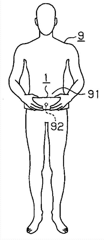
[0032] Such as figure 1 As shown, the body composition measurement device 1 as a body fat measurement device is in contact with the measured portion of the human body 9 . In this example, the body composition measurement device 1 measures body fat in the abdomen 91 . For example, the body composition measuring device 1 is aligned with the navel 92 and positioned relative to the abdomen 91 .
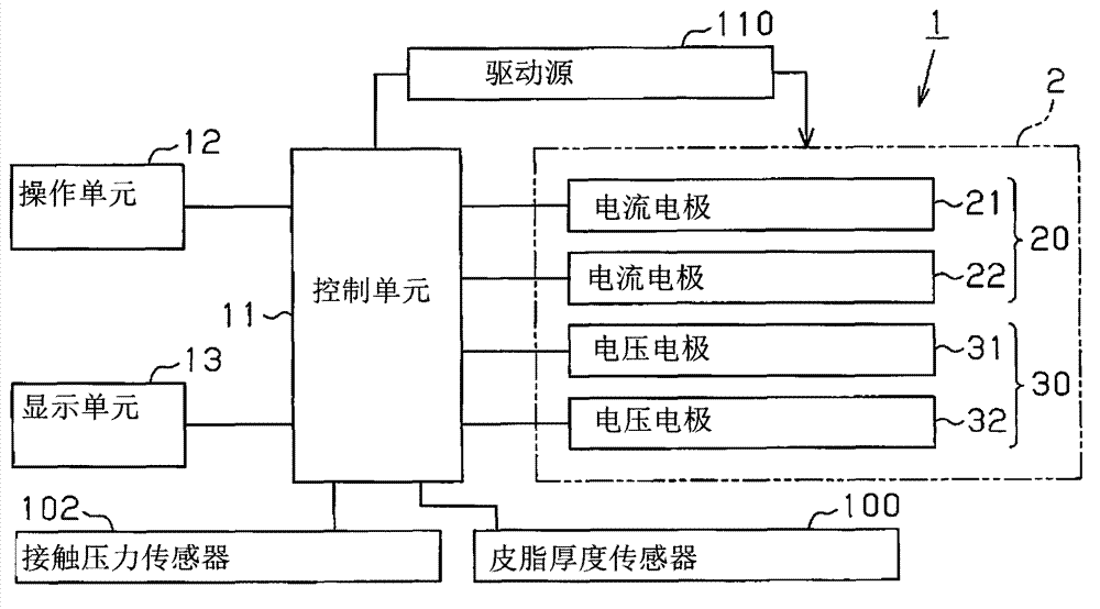
[0033] Such as figure 2 As shown, the body composition measurement device 1 includes an electrode group 2 , a control unit 11 , an operation unit 12 , and a display unit 13 . Electrode group 2 is used to measure body composition. The control unit 11 controls the body composition measurement with the electrode group 2 . The operation unit 12 operates the body composition measurement device 1 . The display unit 13 displays the measurement results of body ...
no. 2 example
[0100] now refer to Figure 7 A body composition measurement device 1 according to a second embodiment will be described. Elements identical to corresponding elements of the first embodiment are given similar or identical reference numerals. Such elements are not described in detail.
[0101] The body composition measuring device 1 of the second embodiment further includes a detector 70 which detects that the width measuring units 50L and 50R have moved toward the left and right points of the abdomen 91 and that the surfaces 50La and 50Ra of the width measuring units 50L and 50R have moved. Contact is made with the abdomen 91 . The detectors 70 are each provided on the surfaces 50La and 50Ra of the width measuring units 50L and 50R that come into contact with the abdomen 91 of the user.
[0102] The detector 70 is connected to the control unit 11 by wires. Each detector 70 outputs a detection signal to the control unit 11 when it is detected that the surfaces 50La and 50Ra...
no. 3 example
[0114] now refer to Figure 8 A body composition measurement device 1 according to a third embodiment will be described. Elements identical to corresponding elements of the first embodiment are given similar or identical reference numerals. Such elements are not described in detail.
[0115] The body composition measuring device 1 of the third embodiment is configured such that movement of any one of the left side width measuring unit 50L and the right side width measuring unit 50R causes the other of the left side width measuring unit 50L and the right side width measuring unit 50R to move. .
[0116] like Figure 8 As shown, the body composition measuring device 1 of the third embodiment includes a left rotatable link gear 75L and a right rotatable link gear 75R provided on the main body 41 and meshing with each other. The gear 75L meshes with the pinion 62L, and the gear 75R meshes with the pinion 62R.
[0117] The body composition measuring device 1 of the third embod...
PUM
 Abstract
Description
Claims
Application Information