Supercharge Your Innovation With Domain-Expert AI Agents!

Electric power tool

一种电动工具、本体部的技术,应用在制造工具、轻便机动装置等方向,能够解决连接至皮带、难锁止构件等问题

Inactive Publication Date: 2011-04-27
PANASONIC CORP
View PDF13 Cites 4 Cited by
  • Summary
  • Abstract
  • Description
  • Claims
  • Application Information

AI Technical Summary

Problems solved by technology

This creates a problem of difficulty in attaching the locking member to the belt

Method used


Image

  • Electric power tool
  • Electric power tool
  • Electric power tool

Examples


Embodiment Construction

[0031] An embodiment of the power tool according to the present invention will be described in detail below with reference to the accompanying drawings forming a part of the present invention.

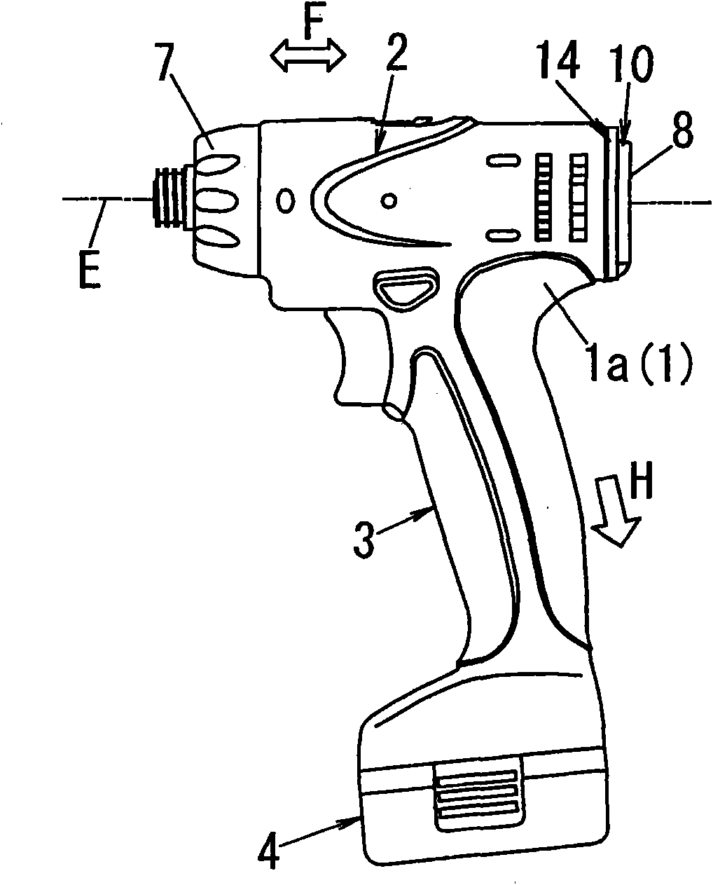
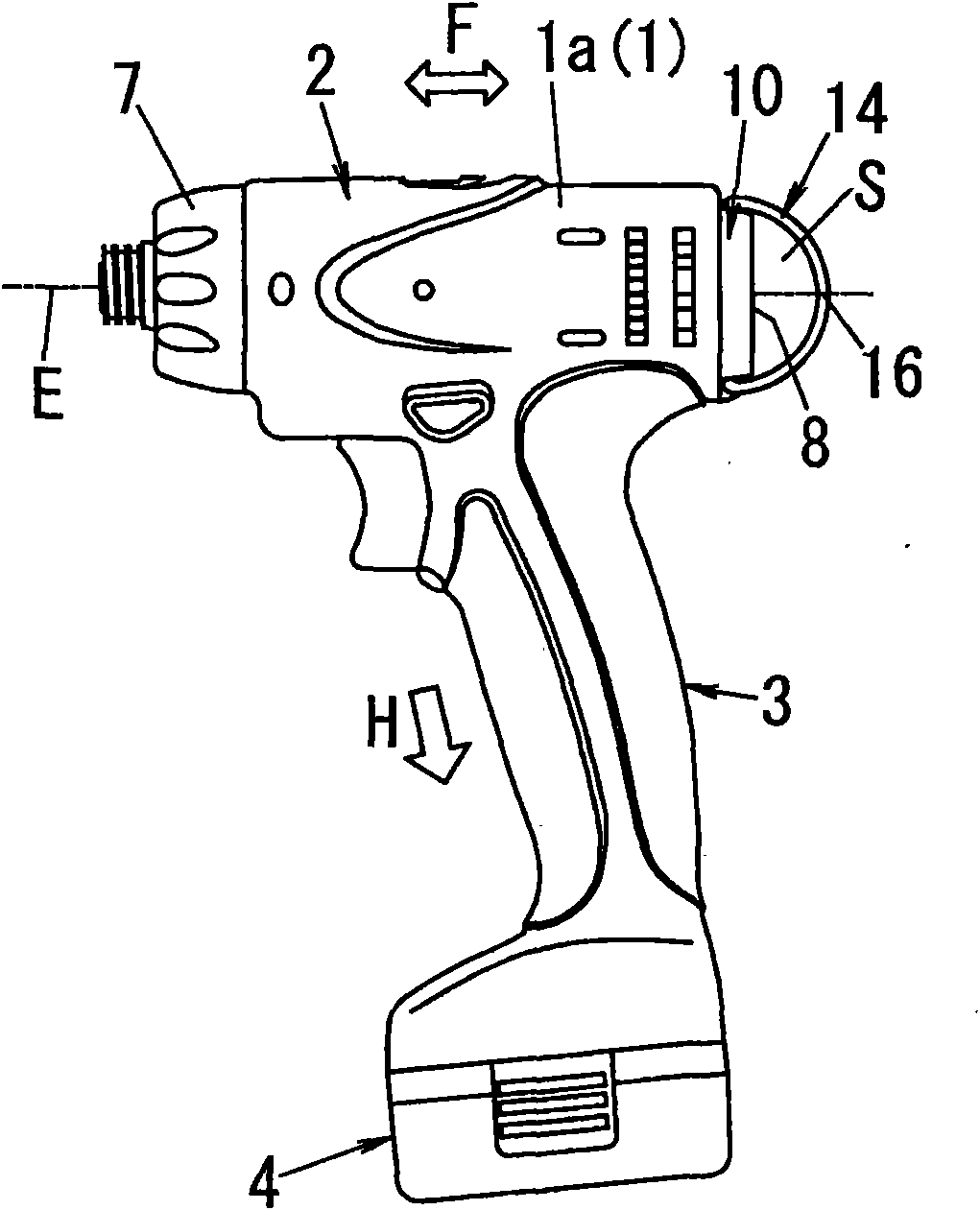
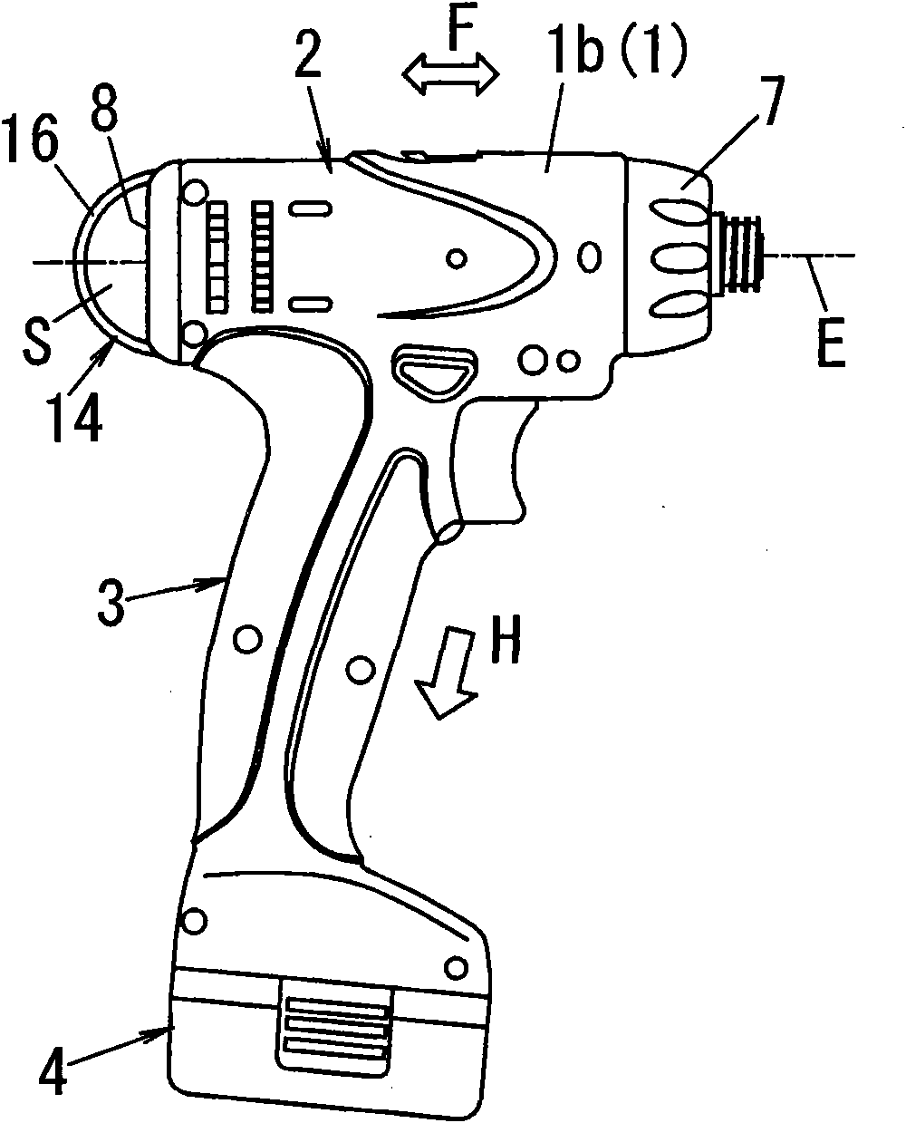
[0032] Referring to FIG. 1 , an electric tool according to the present invention includes a tubular body portion 2 for outputting rotational driving force at one end thereof, a gripping portion 3 extending from the body portion 2 in an intersecting relationship with the axis of the body portion 2, and The battery pack part 4 is detachably connected to the tip end of the grip part 3 in the extending direction H. The housing 1 forming the housing of the body portion 2 and the grip portion 3 is divided into two parts along the extending direction H of the grip portion 3 by the center line of the body portion 2 .

[0033]In the following description, the left half of the housing 1 having the body portion 2 and the grip portion 3 of the left housing will be referred to as "left housing 1a",...


PUM


Abstract

The invention relates to an electric power tool, which comprises a main body for outputting a rotational force at one end thereof, a grip part provided to extend from the main body in an intersecting relationship with the body part and a pull ring equipped at the other end of the main body for hanging the main body.The pull ring is configured to ensure that, if the main body is suspended from the pull ring with the pull ring as a pivot point, the electric power tool is kept by a weight balance in a horizontal posture in which the extension direction of the grip part is substantially orthogonal to the vertical direction or an inclined horizontal posture in which the joint portion of the main body and the grip part is positioned at the upper side.

Description

technical field [0001] The present invention relates to a power tool, and more particularly to a holder unit for holding the power tool during transportation. Background technique [0002] Typically, a portable power tool such as an electric drill or an impact driver is held by the user's belt with a locking element such as a hook fastened to the belt, as in Japanese Patent Publication Nos. 2004-255503 and 2005-313322 As disclosed in the application, this is the case where the user is moving to the site or performing work preparations, such as the task of mounting a workpiece to which rotational drive is to be output. [0003] For example, Japanese Patent Application Laid-Open No. 2004-255503 discloses an electric power tool including a grip portion, a drive portion (body portion) respectively provided on the upper side of the grip portion, and a battery pack chamber (battery pack) base. The legs of the hooks for the leash are attached to the side walls of the base. The h...

Claims


Application Information

Patent Timeline
Patent Type & Authority Applications(China)
IPC IPC(8): B25F5/00B25F5/02
CPCB25F5/02
Inventor 松本宏司中村雅道汤浅秀和
Owner PANASONIC CORP
Features
  • R&D
  • Intellectual Property
  • Life Sciences
  • Materials
  • Tech Scout
  • Unparalleled Data Quality
  • Higher Quality Content
  • 60% Fewer Hallucinations
Learn More