Electrical power tool

a power tool and hand-held technology, applied in the field of hand-held electrical power tools, can solve the problems of the weight of the electrical power tool is not uniform, etc., and achieves the effect of increasing the discharge capacity, reducing the operability of the electrical power tool, and increasing the voltag

Inactive Publication Date: 2015-12-24
MAKITA CORP
View PDF8 Cites 344 Cited by
  • Summary
  • Abstract
  • Description
  • Claims
  • Application Information

AI Technical Summary

Benefits of technology

[0003]In the electrical power tool described above, with regard to electrical power supplied from the rechargeable battery, there is a need for an increased voltage or an increased discharge capacity. Therefore, in order to meet such a need, for example, an electrical power tool to which two general-purpose rechargeable batteries can be attached has been developed. However, when the two rechargeable batteries are attached to the tool main body without any change in the tool main body, the two rechargeable batteries attached thereto may cause an imbalance in weight of the electrical power tool. This may reduce operability of the electrical power tool.
[0004]The present invention has been made in view of the circumstances. It is an object of the present invention to provide a handheld electrical power tool that is used to perform a screw tightening operation or other such operations while it is held in hand, in which a need for an increased voltage and an increased discharge capacity in the electrical power tool can be met while an operability of the electrical power tool can be restricted from being deteriorated.
[0007]Further, because the motor shaft of the electrical power tool extends in the longitudinal direction, the volume of the rechargeable batteries may be aligned with the direction in which the motor shaft extends. Thus, the volume of the rechargeable batteries may be elongated in the direction in which the motor shaft of the electrical power tool extends. Therefore, the electrical power tool having the rechargeable batteries can be reduced in size as a whole. As a result, when the electrical power tool is used to perform a screw tightening operation or other such operations while it is held in hand, good usability of the electrical power tool can be prevented from being reduced.

Problems solved by technology

However, when the two rechargeable batteries are attached to the tool main body without any change in the tool main body, the two rechargeable batteries attached thereto may cause an imbalance in weight of the electrical power tool.
This may reduce operability of the electrical power tool.

Method used


Image

  • Electrical power tool
  • Electrical power tool
  • Electrical power tool

Examples


first embodiment

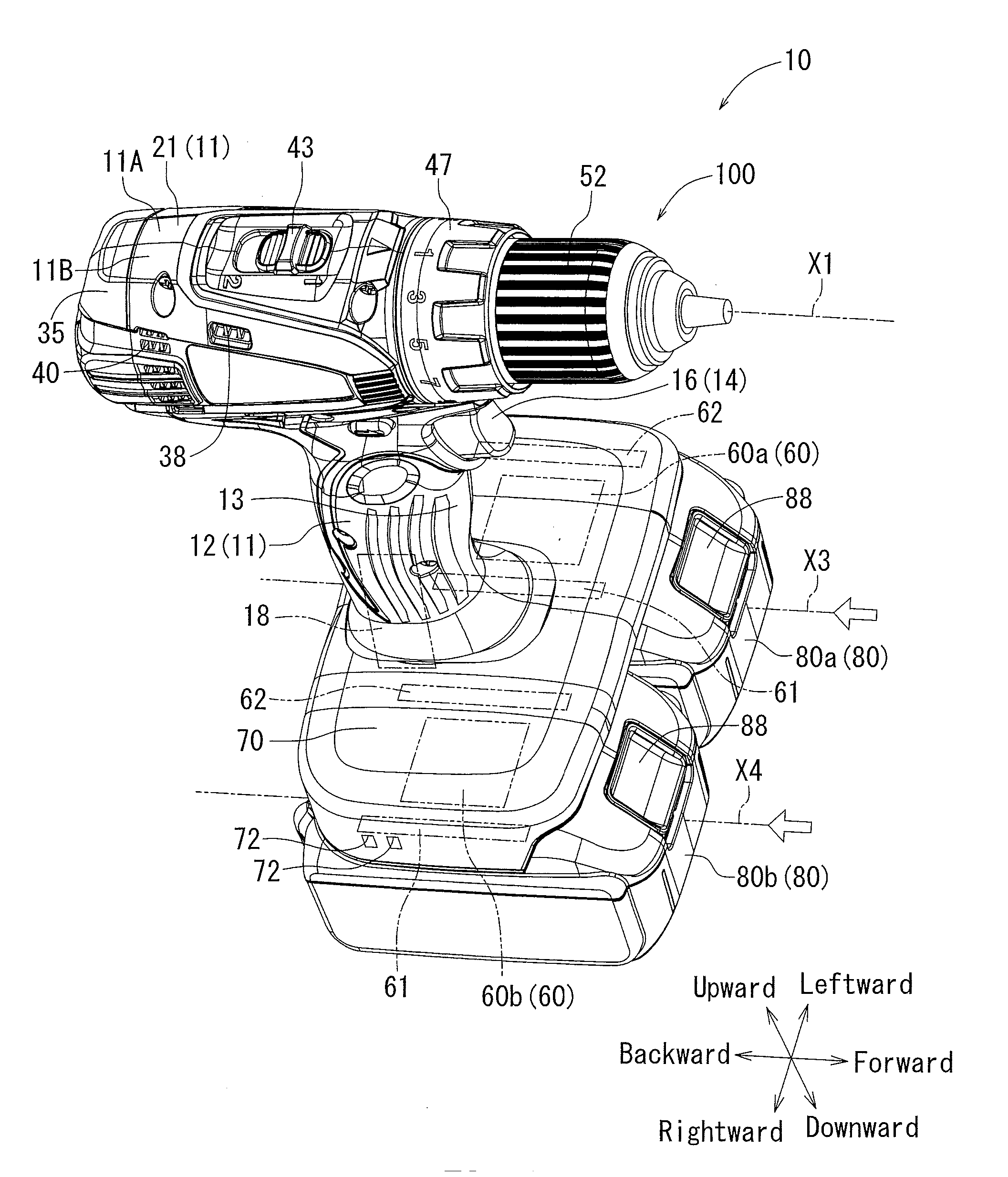
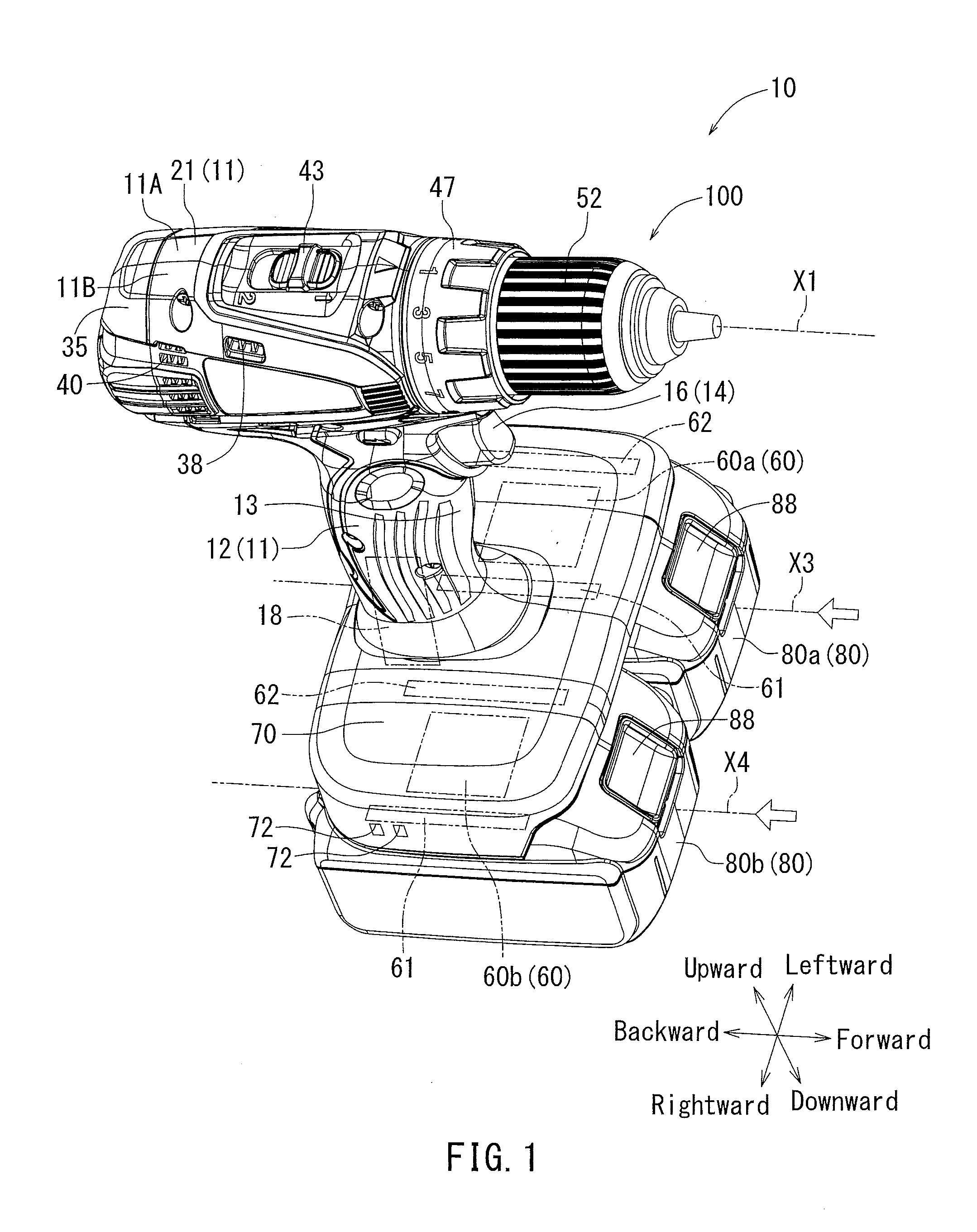
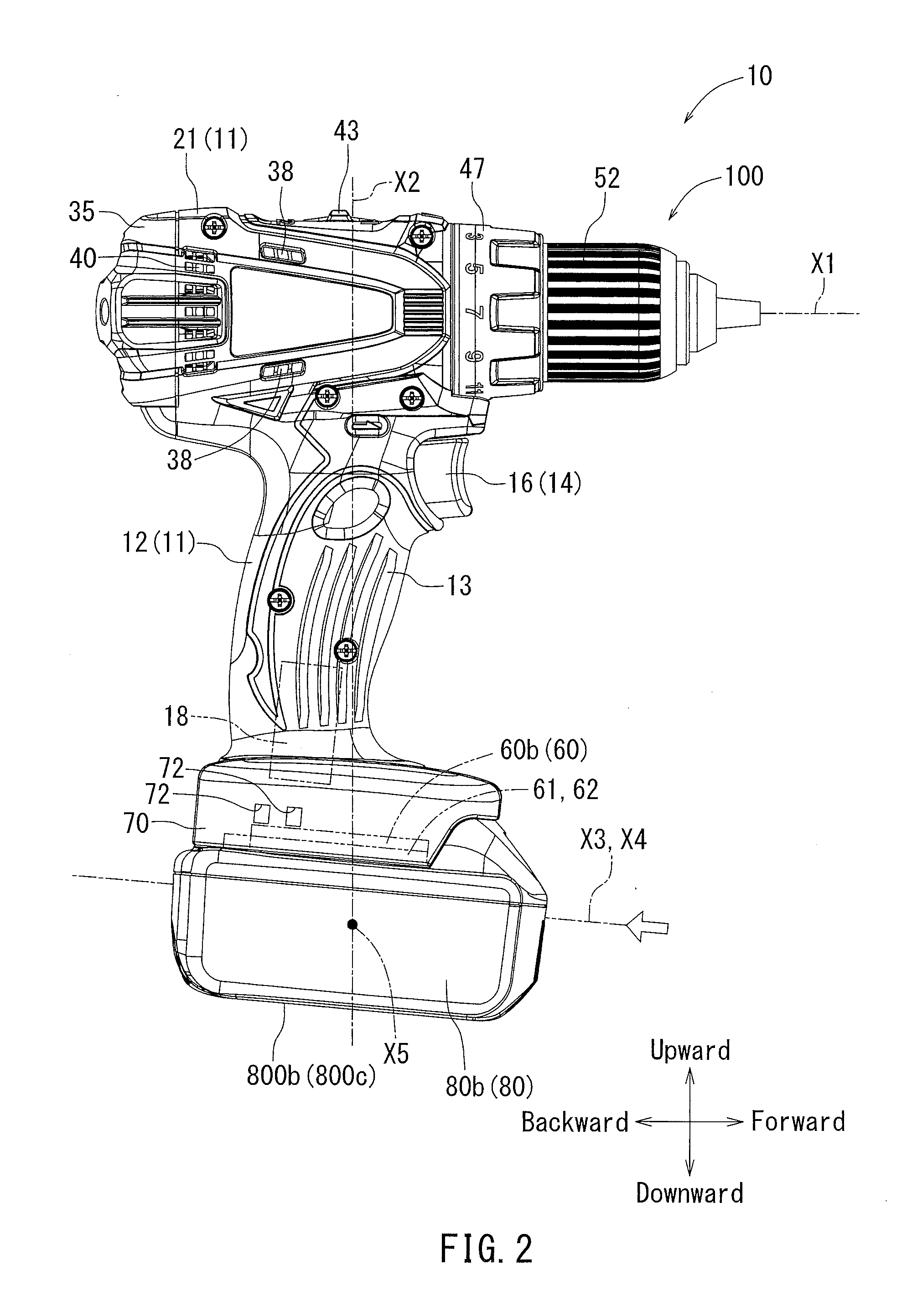
[0065]Next, a first embodiment of the present invention will be described with reference to FIGS. 1 to 9. In FIG. 1, a reference numeral 10 shows a driver drill corresponding to an electrical power tool according to the present invention. Further, FIG. 1 is a perspective view of the driver drill 10 of the first embodiment, which view shows an external appearance thereof. FIG. 2 is a side view of the driver drill 10 shown in FIG. 1. FIG. 3 is a plan view of the driver drill 10 shown in FIG. 1. FIG. 4 is a bottom view of the driver drill 10 shown in FIG. 1. FIG. 5 is an internal structural diagram of the driver drill 10 shown in FIG. 1, which view shows a halved internal structure. FIG. 6 is a sectional view taken along line (VI)-(VI) of FIG. 5, which view shows an internal structure. FIG. 7 is a perspective view of rechargeable batteries 80 to be attached to battery attachment portions 60 by sliding the same. FIG. 8 is an enlarged view of a battery terminal connecting portion 600 sho...

second embodiment

[0090]Next, a second embodiment modified from the first embodiment described above will be described with reference to FIGS. 10 to 13. Further, other embodiments including the second embodiment are different from the first embodiment only in the structure of the battery attachment portions 60 of the driver drill 10. Therefore, elements that are the substantially same as the first embodiment will be identified by the same reference numerals used in the first embodiment and a detailed description of such elements may be omitted. In comparison with the driver drill 10 of the first embodiment, in a driver drill 10A of the second embodiment, slide-fitting directions of the rechargeable batteries 80a and 80b may respectively be reversed. That is, both of a first battery attachment portion 60Aa (60A) and a second battery attachment portion 60Ab (60A) of the second embodiment may respectively be directed in directions opposite to the first battery attachment portion 60a (60) and the second ...

third embodiment

[0092]Next, a third embodiment modified from the first embodiment described above will be described with reference to FIGS. 14 to 17. In comparison with the driver drill 10 and 10A of the first and second embodiments, in a driver drill 10B of the second embodiment, one of the slide-fitting directions of the rechargeable batteries 80a and 80b may be reversed. That is, a first battery attachment portion 60Ba (60B) of the third embodiment may have the same structure as the first battery attachment portion 60a (60) of the first embodiment whereas a second battery attachment portion 60Bb (60B) of the third embodiment may have the same structure as the second battery attachment portion 60b (60) of the second embodiment. Even in the driver drill 10B of the third embodiment thus constructed, the substantially same effects as the driver drill 10 of the first embodiment may be produced. Further, in the driver drill 10B of the third embodiment, the fitting directions of the juxtaposed recharge...


PUM


Abstract

A driver drill may have two battery attachment portions to which two rechargeable batteries can be attached. Therefore, the driver drill can meet a need for an increased voltage or an increased discharge capacity. Further, the two battery attachment portions may be constructed as slide-fitting battery attachment portions. A combined gravity center of the rechargeable batteries attached to the first and second battery attachment portions may be positioned on a vertical line through a gravity center of a tool main body in a condition in which the two rechargeable batteries are detached therefrom.

Description

TECHNICAL FIELD[0001]The present invention relates to a handheld electrical power tool represented by a driver drill that is used to perform a screw tightening operation or a drilling operation while it is held in hand.BACKGROUND ART[0002]Conventionally, a handheld electrical power tool used to perform a screw tightening operation or a drilling operation while it is held in hand is known (for example, JP 2003-191113). Examples of the handheld electrical power tool are an electrical driver, an electrical drill, a driver drill, a vibratory driver drill and an impact driver drill. This type of electrical power tool includes an electrical motor to function as a drive source. The motor is received in a tool main body of the electrical power tool. A grip portion to be gripped by a worker is formed in an outer housing of the power tool. A deceleration mechanism, a power transmission interruption mechanism and other such mechanisms are disposed in a front portion of the tool main body. A sp...

Claims


Application Information

Patent Timeline
Patent Type & Authority Applications(United States)
IPC IPC(8): B25F5/02
CPCB25F5/02
Inventor ITO, MIYABIMURAMATSU, KAZUO
Owner MAKITA CORP
Why Eureka
Try Eureka