Surgical switch mode power supply and surgical DC power tool

a power supply and switch mode technology, applied in the field of surgical switch mode power supply, can solve the problems of time-consuming and labor-intensive battery charging, and each battery or accumulator can store only a limited amount of energy,

Active Publication Date: 2012-08-14
AESCULAP AG
View PDF38 Cites 247 Cited by
  • Summary
  • Abstract
  • Description
  • Claims
  • Application Information

AI Technical Summary

Problems solved by technology

Such drive machines, for example, drills or saws have the disadvantage that each battery or each accumulator can store only a limited amount of energy.
The charging of the battery does, however, require time.

Method used


Image

  • Surgical switch mode power supply and surgical DC power tool
  • Surgical switch mode power supply and surgical DC power tool
  • Surgical switch mode power supply and surgical DC power tool

Examples


first embodiment

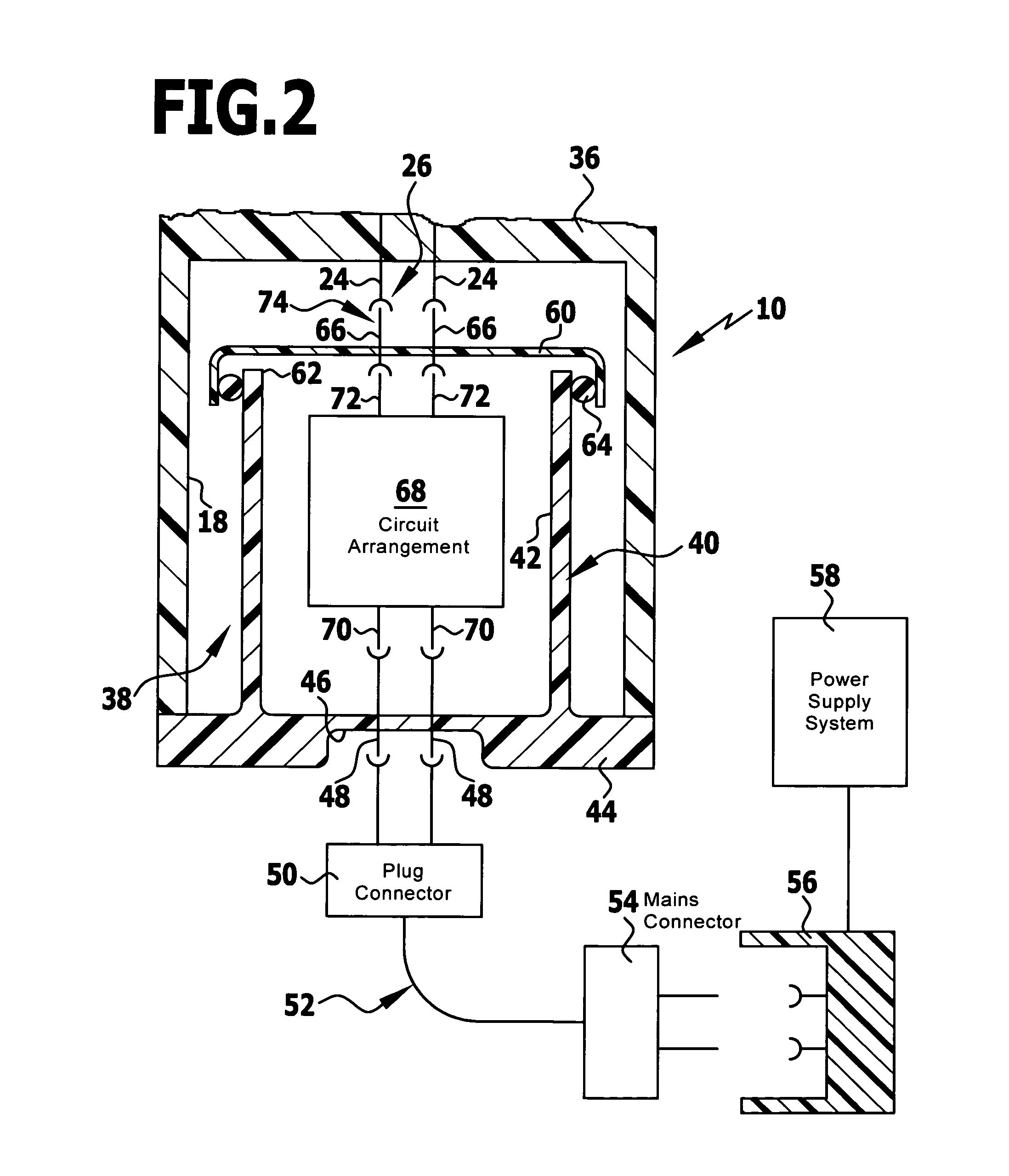
[0065]a switch mode power supply 38 is illustrated schematically in FIG. 2. It comprises an essentially sleeve-shaped housing 40 of the switch mode power supply which defines an essentially hollow cylindrical circuit receptacle 42. A base 44 of the housing 40 of the switch mode power supply is widened in a radial direction in a flange-like manner and thus forms at the same time a housing cover for closing the energy supply receptacle 18. A recess 46 with connection contacts 48 is provided on an outer side of the base 44, the contacts together forming a low-temperature connector socket and being connectable to a plug connector 50 of a mains connection cable 52 which, on the other hand, has at its other end a mains connector 54 which can be connected to a connector socket 56 connected to a power supply system 58.

[0066]The housing 40 of the switch mode power supply further comprises a housing cover 60 of the switch mode power supply for closing a housing opening 62 of the switch mode p...

second embodiment

[0069]a surgical switch mode power supply is illustrated schematically in FIG. 3 and provided, altogether, with the reference numeral 76. The switch mode power supply 76 differs from the switch mode power supply 38 only in that the housing 40 of the switch mode power supply comprises no housing cover 60 for the switch mode power supply. The DC connection contacts 72 of the circuit arrangement 68 of the switch mode power supply therefore form, themselves, an interface 74 of the switch mode power supply which can be brought into engagement with the interface 26. The seal 64 is arranged on the housing 40 of the switch mode power supply so as to surround the housing opening 62 of the switch mode power supply. It serves the purpose of sealing the circuit receptacle 42 relative to the housing 36. Optionally, an additional seal 78 can be provided which seals the flange-like widened portion formed by the base 44, in addition, relative to the housing 36 of the DC power tool 10. The seal 78 c...

third embodiment

[0071]a switch mode power supply according to the invention is illustrated schematically in FIG. 4 and provided, altogether, with the reference numeral 138. It has a great similarity to the switch mode power supply 38 and so parts of the switch mode power supply 138 which correspond to parts of the switch mode power supply 38 are provided with reference numerals which have the same two end numbers. The essential difference to the switch mode power supply 38 described in conjunction with FIG. 2 is to be seen in the fact that a separate housing cover 180 is provided, with which the energy supply receptacle 18 can be closed. A fluid-tight / germ-tight sealing is achieved by a seal 182 which is arranged between the housing cover 180 and the housing 36 and is held either on the housing cover 180 or on the housing 36. A low-temperature connector socket is formed on the housing cover 180 by providing a recess 146 which points outwards and on which fourth electrical contacts 184 are arranged ...


PUM


Abstract

In order to improve a surgical DC power tool such that it can be operated, where applicable, under sterile conditions, in particular, using conventional DC voltage supplies, a surgical switch mode power supply for a surgical DC power tool is provided. The switch mode power supply includes a switch mode power supply circuit arrangement, a switch mode power supply housing and a circuit receptacle formed in the housing of the switch mode power supply for accommodating the circuit arrangement of the switch mode power supply. The housing of the switch mode power supply has a switch mode power supply interface which is designed in such a manner that it can be brought into engagement with and / or connected to an interface of the DC power tool provided for a mains-independent energy source. Furthermore, an improved surgical DC power tool having such a power supply is provided.

Description

CROSS-REFERENCE TO RELATED APPLICATIONS[0001]This application is a continuation of international application number PCT / EP2007 / 062859 filed on Nov. 27, 2007.[0002]The present disclosure relates to the subject matter disclosed in international application number PCT / EP2007 / 062859 of Nov. 27, 2007 and German application number 10 2006 058 867.3 of Dec. 7, 2006, which are incorporated herein by reference in their entirety and for all purposes.FIELD OF THE INVENTION[0003]The present invention relates to a surgical switch mode power supply generally, and more specifically to a surgical switch mode power supply for a surgical DC power tool.[0004]Furthermore, the present invention relates to a surgical DC power tool generally, and more specifically to a surgical DC power tool with a housing, a DC power consumer accommodated in the housing and an interface for a mains-independent energy source.BACKGROUND OF THE INVENTION[0005]Surgical DC power tools are used in surgery, for example, in the ...

Claims


Application Information

Patent Timeline
Patent Type & Authority Patents(United States)
IPC IPC(8): A61B18/04
CPCA61B17/1628H02M7/003A61B2017/00734A61B2017/00477A61B17/16
Inventor KAHLER, THOMASHOEGERLE, ROLAND
Owner AESCULAP AG
Why Eureka
Try Eureka